Download
1 / 80
2.49k likes | 5.47k Vues
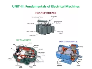
UNIT-III: Fundamentals of Electrical Machines. TRANSFORMER. Principle of Operation: Mutual inductance and mutual coupling phenomena in transformer Construction Working Concept of Turns Ratio Applications Transformer on DC Autotransformer Instrument transformers.

E N D
TRANSFORMER Principle of Operation: Mutual inductance and mutual coupling phenomena in transformer • Construction • Working • Concept of Turns Ratio • Applications • Transformer on DC • Autotransformer • Instrument transformers
In Brief, A transformer is a static electrical device that transfers electrical energy between two or more circuits through electromagnetic induction.
Principle of operation It is based on principle of MUTUAL INDUCTION. According to which an e.m.f. is induced in a coil when current in the neighbouring coil changes.
PRINCIPLE OF TRANSFORMERIt works on the principle of Electromagnetic induction. The current flowing in the primary winding of the transformers creates a magnetic field, magnetic flux flows to the secondary side of the transformers, which induces EMF in the winding and current flows when the circuit is closed. A varying current in one coil of the transformer produces a varying magnetic field, which in turn induces a varying electromotive force (emf) or "voltage" in a second coil.
TRANSFORMER ON DC SUPPLY • What will happen if the Primary of a Transformer is Connected to D.C. Supply????
Auto-Transformer An Auto-transformer is an electrical transformer with only one winding.
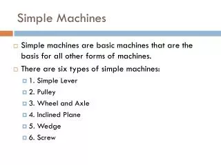
DC MACHINES • DC MOTOR • DC GENERATOR • Working principles • Classification • Starting of DC Machines • Speed control of DC Motor • Applications of dc motors
Review of magnetism Lines of flux define the magnetic field and are in the form of concentric circles around the wire. The magnetic lines around a current carrying conductor leave from the N-pole and re-enter at the S-pole. "Left Hand Rule" states that if you point the thumb of your left hand in the direction of the current, your fingers will point in the direction of the magnetic field. The flow of electrical current in a conductor sets up concentric lines of magnetic flux around the conductor.
Fleming’s left hand rule Used to determine the direction of force acting on a current carrying conductor placed in a magnetic field . The middle finger , the fore finger and thumb of the left hand are kept at right angles to one another . The middle finger represent the direction of current The fore finger represent the direction of magnetic field The thumb will indicate the direction of force acting on the conductor . This rule is used in motors.
Fleming’s left hand rule Used to determine the direction of force acting on a current carrying conductor placed in a magnetic field . The middle finger , the fore finger and thumb of the left hand are kept at right angles to one another . The middle finger represent the direction of current The fore finger represent the direction of magnetic field The thumb will indicate the direction of force acting on the conductor . This rule is used in motors.
Are DC generators that convert mechanical energy to DC electric energy. Are DC motors that convert DC electric energy to mechanical energy. What are DC Machines? • DC machine can be used as a motor or as a generator. • DC Machine is most often used for a motor.
DC MOTOR: INTRODUCTION • DC motors are found in many special industrial environments • Motors drive many types of loads from fans and pumps to presses and conveyors • The major advantages of dc machines over generators are easy to control speed and torque regulation. • However, their application is limited to mills, mines and trains. As examples, trolleys and underground subway cars may use dc motors. • In the past, automobiles were equipped with dc dynamos to charge their batteries, but now dynamos are replaced by alternators.
CONSTRUCTION OF DC MACHINES Rotor of a dc motor DC motor stator
DC machines, like other electromechanical energy conversion devices have two sets of electrical windings field windings - on stator amarture windings - on the rotor. DC Machines Construction .
DC Machines Construction • The stator of the dc motor has poles, which are excited by dc current to produce magnetic fields. • In the neutral zone, in the middle between the poles, commutating poles are placed to reduce sparking of the commutator. The commutating poles are supplied by dc current. • Compensating windings are mounted on the main poles. These short-circuited windings damp rotor oscillations.
DC Machines Construction • The poles are mounted on an iron core that provides a closed magnetic circuit. • The motor housing supports the iron core, the brushes and the bearings. • The rotor has a ring-shaped laminated iron core with slots. • Coils with several turns are placed in the slots. The distance between the two legs of the coil is about 180 electric degrees.
DC Machines Construction • The coils are connected in series through the commutator segments. • The ends of each coil are connected to a commutator segment. • The commutator consists of insulated copper segments mounted on an insulated tube. • Two brushes are pressed to the commutator to permit current flow. • The brushes are placed in the neutral zone, where the magnetic field is close to zero, to reduce arcing.
DC Machines Construction • The commutator switches the current from one rotor coil to the adjacent coil, • The switching requires the interruption of the coil current. • The sudden interruption of an inductive current generates high voltages . • The high voltage produces flashover and arcing between the commutator segment and the brush.
Principle of Operation The generated voltage of a DC machines having (p) poles and (Z) conductors on the armature with (a) parallel path between brushes as below : where K = pZ /(2πa) = machine constant The mechanical torque which also equal to electromagnetic torque, is found as follows: In the case of a generator, m is the input mechanical torque, which is converted to electrical power. For the motor, e is developed electromagnetic torque, which used to drive the mechanical load.
Principle of Operation ARMATURE winding are defined as the winding which a voltage is induced. FIELD windings are defined as the windings that produce the main flux in the machines. The magnetic field of the field winding is approximately sinusoidal, thus AC voltage is induced in the armature winding as the rotor turns under the magnetic field of stator. The COMMUTATOR and BRUSH combination converts the AC generated voltages to DC.
Principle of Operation The induced or generated DC voltage (EA) appearing between the brushes is a function of the field current (IF) and the speed of rotation () of the machine. This generated voltage is : Where K’ = voltage constant = rotation per min If the losses of the DC machine are neglected, the electrical power is equal to the mechanical power

![FUNDAMENTALS OF ELECTRICAL ENGINEERING [ ENT 163 ]](https://cdn1.slideserve.com/2962351/fundamentals-of-electrical-engineering-ent-163-dt.jpg)