Charging System Fundamentals
Charging System Fundamentals. Chapter 30. Objectives. Explain electrical generation principles Describe AC generator parts Explain the operation of a voltage regulator. Introduction. Charging system Important part of electrical system

Charging System Fundamentals
E N D
Presentation Transcript
Charging System Fundamentals Chapter 30
Objectives • Explain electrical generation principles • Describe AC generator parts • Explain the operation of a voltage regulator
Introduction • Charging system • Important part of electrical system • Allows battery to maintain charge and operate accessories
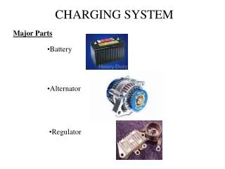
Charging System • Charging system components • Alternator and voltage regulator • Dash light or gauge • Related wiring • Charging replenishes the battery • Output increased when load causes battery voltage to drop • Starter motor is a large load on the battery • AC generator recharges battery and supplies electrical needs
Direct Current (DC) Generators • Older cars used DC generators • Produces AC • Output is DC because its commutator has brushes on north and south poles • Drawbacks • More current must flow through brushes • Brushes wear out • Speed limited to 10,000 rpm • Do not produce enough output at slow speeds to supply electrical accessories
AC Generator/Alternator • Alternator is an AC generator • Electromagnet passes across wire to induce voltage • Stator: stationary conductor • Rotor: rotating electromagnetic field
Rotor Construction • Rotor: magnetic field that rotates within the stator’s wire windings • Very little clearance to maintain strong field • Field coil has electrical wire wound around a shaft • Poles fit into each other • Make several pairs of north and south poles • Increases magnetic flux • Average rotor can spin at about 13,500 rpm
Stator Windings • Three sets of windings wrapped around slots in laminated round iron frame (i.e., core) • Each winding has two leads: one for current to enter and one to exit
Rectifier Construction • Diode rectifier converts AC to DC • When AC current reverses, the diode blocks • A pair of diodes is used for each stator winding • Three positive diodes are mounted in a heat sink • Three negative diodes mounted in the alternator frame • Three phases of AC are rectified • Result is almost uniform DC voltage
AC Generator Bearings • Rotor is supported in alternator housing using ball or roller bearings • Bearings are usually sealed and packed with grease • Front bearing fits into indent in the case • Rear bearing is pressed-fit into the case • Rotor shaft slides into rear bearing • AC generator fan • Cooling fan draws air into AC generator
Voltage Regulator • Controls current passing through windings of electromagnetic field in the rotor • Determines amount of current produced in stator • Increases current output when charging system voltage is low • Electronic voltage regulators • No moving parts or contacts: very reliable • Zener diode conducts electricity when a certain voltage is reached
Voltage Regulator (cont'd.) • Computer voltage regulation/pulse • Voltage regulation on late-model vehicles is done by the on-board computer, or powertrain control module • Electronic voltage regulation: can cycle 10-7,000 times per second • Pulse width modulation: turning alternator on and off rapidly
Charging System Indicators • Charge indicators • Warning light • Voltmeter • Ammeter • AC generator warning light • Wired into charging circuit • Voltmeter indicator • Shows system voltage when engine is running • Ammeter indicator • Gives current amount flowing to or from battery
High-Voltage Charging Systems • Important dates and concepts • 1970: automobile required about 500 watts • 2008: vehicle requires about 4,000 watts • 2020: BAS systems will be included on all internal combustion engine vehicles • BAS systems use 42-volt electrical systems with a 36-volt battery pack • BAS motor/generator: larger than conventional AC generator
High-Voltage Charging Systems (cont'd.) • Hybrid vehicles • More electrically powered components • Use a generator with inverter/converter • Converts battery pack voltage to low voltage to power the computer and accessories