Download
1 / 36
360 likes | 409 Vues
This overview delves into system modeling and architecture, exploring heterogeneous task graphs, rising abstraction levels, and models of computation like data flow and synchronous models. It covers embedded software and hardware aspects, including communication protocols and real-time operating systems. The discussion extends to user interfaces, speech processing, and system design considerations for communication systems. The interplay of different models of computation and their integration into systems is a focal point, emphasizing the importance of synchronization and static data flow in system design. Lastly, the integration of SDL and Matlab for system modeling and synchronization is addressed, highlighting the benefits of leveraging different languages for comprehensive system design.

E N D
System Specification Fundamentals Axel Jantsch, Royal Institute of Technology Stockholm, Sweden
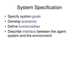
Overview • Motivation • Models of Computation • Data Flow • Synchronous Models • Discrete Event Models • SDL - Matlab Integration • Summary
System Model and Architecture Heterogeneous Task Graph Heterogeneous Architecture
Rising Abstraction Levels Software • Machine code • Assembler code • Subroutines, libraries Hardware • Polygons • Gates • Blocks (ALUs, Multipliers, FSMs, etc) • Functional blocks (Filters, MPEG codecs, Protocols, etc.) System • Functional blocks (Filters, MPEG codecs, Protocols, etc.) • Features (GSM connection, GPS Modules, Speech recognision, etc.)
Heterogeneity of Expertise Embedded Software Hardware RF/Mixed Signal Communication Protocols Real-time Operating System Digital Signal Processing User Interface Speech Processing System Design Communication Systems
Models of Computation (MoC) • Raise timing abstraction • Raise communication abstraction • Different MoCs serve different needs • Different MoCs can be integrated into the system • MoCs to be discussed: • Dataflow • Synchronous MoC • Timed MoC
Dataflow Process Networks • Networks of actors connected with streams • Hierarchy of networks • Communication is buffered with unbounded FIFOs A B C D
f(x,y) x A y g(x,y) Functional Actors • No side effects • For the same input values produce the same output values • Functional for each firing cycle • Functional over the entire streams
0 0 0 4 0 8 0 A B C 1 2 2 D 2 A 2 4 B C 2 1 2 Schedule: AABAABCD 2 2 D 1 Static Data Flow • The number of tokens consumed and produced by each process is constant. • A static schedule can always be found, if it exists, and • The maximum buffer requirements can be computed statically.
synchronized <Initialize memory> foreach period do <Read inputs> <Compute outputs> <Update memory> end • Assumption: The system reacts rapidly enough to perceive all external events in suitable order. Perfect Synchrony • Perfect synchrony assumption: • Computation takes no time • Communication takes no time (synchronous broadcast)
Features of Synchronous Languages • Deterministic • Amenable to formal analysis • Efficient synthesis • Substitution of equivalent blocks preserves behaviour
P1 P2 P3 P1 P2 P3 Substitution of Equivalent Blocks
P1 P2 P3 P1 P2 P3 ? 1 cycle 1 cycle 1 cycle Clocked Synchronous Models • Computation takes 1 clock cycle • Communication takes no time • Substitution of blocks must consider timing behavour
Discrete Event Models • Event driven dynamics • Events: • Primary input stimuli • Internally generated events • Events have totally ordered time stamps • Components have arbitrary delays • Discrete or continuous time • Most general timing model • Primarily targeted to simulation
A A B 0 delay B 0 delay C C t+ t t t t t t t A B 0 delay C A B 0 delay C Simultaneous Events D delay model
The model allows infinite feed back loops between t and t+1 A t+ t+2 t+3 ... time 0 ... t t+1 ... Delta Time
DE Models are interpreted according to a different timing model: Clocked synchronous model Combinatorial Block Combinatorial Block Register Register Discrete Event Models • Global event queue is a bottleneck • Timing model is close to physical time • Good to simulate timing behaviour of existing components; • Difficult to synthesize • Difficult to formally verify
Heterogeneous System Modelling • Heterogeneous Systems • Different Communities of Engineers • Established Languages with different profiles • Established design flows
B E E B I I A D D A C F F C I I Mixing multiple MoCs MoC I MoC II Well defined mapping Design Language (System C, ...)
SDL and Matlab • SDL • Communicating State Machines • Communication is buffered with infinite FIFOs • Non-deterministic elements • Partially or totally ordered global time • Discrete events govern the execution • Matlab • Data flow model • Demand driven execution • Deterministic • Partially ordered events; no global time • Vector oriented computation
r = f(a)wherea = <a0, a1, …, an>andr = <r0, r1, …, rm> rm … r1 r0 an … a1 a0 f Matlab - SDL Integration: Timing • Equip Matlab with a timing model with totally ordered events Re-interpretation !
Events A B SDL SDL Data streams f g Matlab Matlab Matlab - SDL: Synchronisation • Provide a synchronization mechanism which preserves Matlab’s vector oriented computation
signal Process Composite Signal Flow • Execution Model • Data flow process • Processes may have state • Signals • Signals are sets of events • An event is a (value, tag) pair
event (t0, <v0, v1, …, vn>) (t1, < …>) (t3, < …>) (t2, < …>) signal Signals • Signals • Signals are sets of events • An event is a (value, tag) pair • Sampled Signals • Values are only defined for tags t = t0+nl • Vectorized Signals • Event values are vectors of constant length • Vectorized, sampled signals
(t+4, <v4, v5, v6, v7) (t, <v0, v1, v2, v3) (t+3, v3 ) (t+2, v2) (t+1, v1) Ψh4 (t, v0) (t+3, <v0, v1, v2, v3) (t-1, <…>) (t+3, v3 ) (t+2, v2) (t+1, v1) Ψt4 (t, v0) Vectorization • Head vectorization • Tail vectorization
(t+4, <v4, v5, v6, v7) (t, <v0, v1, v2, v3) (t+3, v3 ) (t+2, v2) (t+1, v1) Ωh4 (t, v0) (t+3, <v0, v1, v2, v3) (t-1, <…>) (t+3, v3 ) (t+2, v2) (t+1, v1) Ωt4 (t, v0) De-Vectorization • Head de-vectorization • Tail de-vectorization
i P o • Head vectorization is not causal • Tail vectorization is causal • Head de-vectorization is causal • Tail de-vectorization is not causal Causality • A process is causal if for all possible input and output streams two output streams never differ earlier than the corresponding two input streams. i1 = p1 α p2o1 = q1 β q2 i2 = p1 γ p3o2 = q1 δ q3 α γ β δ P is causal if and only if tag(α) tag(β)
(t+n+3, v3 ) (t+n+2, v2) (t+n+1, v1) (t+3, v3 ) (t+2, v2) (t+1, v1) (t+n, v0) Δn (t, v0) Causality and Delay Processes • By combining a non-causal process with a delay process, the resulting compound process can be causal • A delay process outputs every input event delayed by a specific time.
B B As=n,n>0 Δn As=n,n>0 C C Safe situation Unsafe situation Constraints on Modelling • Modelling constraints must ensure that processes have data available when they need it.
Applications • Co-Modelling of Matlab and SDL • Causality constraints imply modelling constraints to safely mix Matlab and SDL processes • Timing analysis • Causality constraints can be interpreted as timing constraints derived from the timing of streams • Parallel Simulation • A partition must be a causal process • Only periodic signals may cross partition boundaries
Connecting MoC Domains • Connecting MoC Domains relates time structures • When you connect an U-MoC with a T-MoC or a S-MoC, the U-MoC imports the time structure. • Interfaces can model the time relation • Interface delays can be modeled stochastically or nondeterministically • Channel behaviour becomes more realistic • Time structure relation can be complex
MoC Interface Refinement • Add time interface to precisely define the time structure relation. The relation can be constant, cyclic, deterministic or stochastic. • Refine the protocol to allow reliable communication across the domain boundary with the given time relation. • Model the channel delay if desirable.
MoC Interface RefinementStep 1 – Add time interface MoC I MoC II P Q MoC I MoC II Time relation:3 : 1 P Q
MoC Interface RefinementStep 2 – Refine Protocol MoC I MoC II Time relation:3 : 1 P1 Q1 P2 Q2
MoC Interface RefinementStep 3 – Model Channel Delay MoC I MoC II D[2,5] P1 Time relation:3 : 1 Q1 P2 D[2,5] Q2
Summary • Heterogeneous system modeling is a necessity • Different models of computation continue to coexist • Designers should use MoCs as abstract as possible that still contain the properties of interest. • A thorough understanding of different MoCs and their relation will address many current problems • Different MoCs can be represented in the same or different design languages