Brake System Fundamentals
Brake System Fundamentals. Chapter 71. Basic Brake System. Metal tubing and rubber hose that transmit pressure to the wheel brake assemblies. Mechanical system for applying rear brake assemblies Foot lever for operating the master cylinder and power booster.

Brake System Fundamentals
E N D
Presentation Transcript
Brake System Fundamentals Chapter 71
Basic Brake System • Metal tubing and rubber hose that transmit pressure to the wheel brake assemblies. • Mechanical system for applying rear brake assemblies • Foot lever for operating the master cylinder and power booster. • Hydraulic-piston pump that develops pressure for the brake system. • Vacuum or power steering operated device that assists brake pedal application. • Devices that use system pressure to produce friction for slowing or stopping wheel rotation. Brake linesEmergency brake Brake pedal assemblyMaster cylinder Brake booster Wheel brake assembly
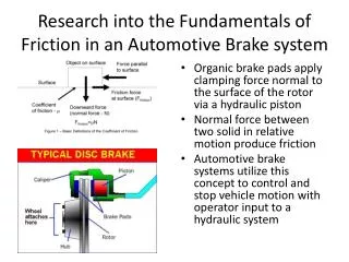
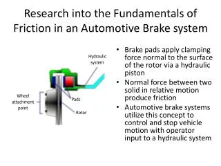
Drum and Disc Brakes • Caliper - assembly that holds the cylinder, piston, and brake pads.
Drum and Disc Brakes • Caliper cylinder - machined hole in the caliper; the piston fits into this cylinder.
Drum and Disc Brakes • Brake pads - friction members pushed against the rotor by the action of the master cylinder, caliper cylinder, and piston.
Drum and Disc Brakes • Rotor - metal disc that uses friction from the brake pads to stop or slow wheel rotation.
Drum and Disc Brakes • Wheel cylinder - houses hydraulic pistons that are forced outward by fluid pressure and is found on drum brakes.
Drum and Disc Brakes • Brake shoes - friction units that are pushed against the rotating brake drum by the action of the wheel cylinder assembly.
Drum and Disc Brakes • Brake Drum - rubs against the brake shoes to stop or slow wheel rotation.
Braking Ratio • Typically the front brakes handle 60-70% of the braking power, while the rear brakes handle 30-40% of the braking. Front wheel drive vehicles have even a higher braking ratio at the front wheels.
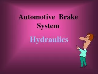
Brake System Hydraulics • Liquids in a confined area will not compress, however, air in a confined area will compress. • When pressure is applied to a closed system, pressure is exerted equally in all directions. • A hydraulic system can be used to increase or decrease force or motion. Pascal’s Law
Brake System Components • Brake Pedal Assembly - Foot lever for operating the master cylinder and power booster.
Brake System Components • Master Cylinder – • It is a foot operated pump that pumps brake fluid. • Helps equalize the pressure required for braking. • Keeps the system full of brake fluid. • It maintains a slight pressure to keep contaminants (air & water) from entering the hydraulic system.
Brake System Components • Brake Boosters • Vacuum brake boosters use engine vacuum to help stop the vehicle. • Hydro-boost systems use pressure created by the power steering pump to help stop the vehicle. • All brake boost systems are designed to help stop the vehicle. Vacuum Booster Hydraulic Booster
Brake Fluid Brake Fluid DOT 3 Standard Brake Fluid DOT 4 Hi-Temp Brake Fluid DOT 5 Silicone Brake Fluid Keep brake fluid in tightly sealed containers. Should be flushed every 2 years regardless of mileage!
Brake System Components Disc Brake Components • 1 Caliper assembly2 Bracket mounting bolt3 Bleed screw4 Dust cap5 Anti-rattle spring6 Guide bolt7 Brake pad wear warning light wire8 Cable clamp9 Brake disc10 Allen bolt11 Shield12 Bolt13 Washer14 Plug15 Plug16 Caliper bracket17 Cable clamp18 Piston seal, piston, dust boot and circlip19 Guide bush repair kit20 Brake pads
Brake System Components Drum Brake Components
Brake Warning Lights • The brake warning light switch warns the driver of a pressure loss in a dual brake system. • The Low-Fluid Warning Light Switch lets the driver know when the brake fluid is low.
Brake System Control Valves • Proportioning Valve is used to equalize braking action in systems with front disc brakes and rear drum brakes. • Metering Valve is used to regulate the pressure going to each wheel cylinder. • Combination Valve is a single unit that functions as a brake warning light switch, a metering valve, and a proportioning valve.
Parking Brakes • Parking brakes provide a mechanical means of applying the brakes. • Parking brakes can use either drum or disc brakes. • Parking brakes should never be used to help stop the vehicle during normal driving. • Parking brakes need periodic inspection and adjustment. A hand operated emergency brake should make 4-5 clicks when engaging it (not more)