Brake Fundamentals
Brake Fundamentals. Chapter 57. Objectives. Explain the basic principles of braking, including friction, pressure, and heat dissipation Describe hydraulic system operation, including master cylinder, control valves, and safety switches Understand the operation of power brakes. Introduction.

Brake Fundamentals
E N D
Presentation Transcript
Brake Fundamentals Chapter 57
Objectives • Explain the basic principles of braking, including friction, pressure, and heat dissipation • Describe hydraulic system operation, including master cylinder, control valves, and safety switches • Understand the operation of power brakes
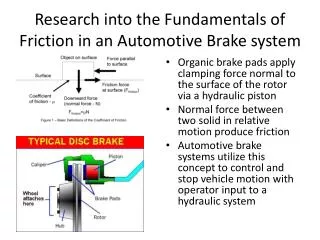
Introduction • Kinetic energy: energy that wants to stay in motion • Apply brakes to stop a car: dry friction changes motion energy to heat energy • Temperature in brake linings can be 600°F • Friction resists movement between surfaces • Coefficient of friction varies • Temperature, rubbing speed, surface condition • During a stop • Vehicle weight shifts to front brakes • Front breaks wear out faster
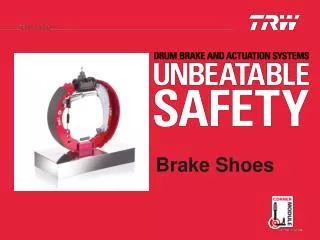
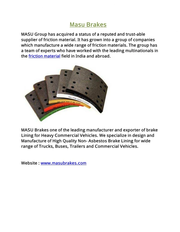
Brake Linings • Linings are bonded or riveted to disc backing • Newer pads integrally molded • Lining types • Asbestos linings: health hazard • Semimetallic linings: sponge iron and steel fibers • Metallic linings: used in heavy-duty and racing conditions • Ceramic linings: use ceramic and copper fibers to control heat
Drum and Disc Brakes • Drum brake systems • Metal brake drums bolted to wheels • Disc brake systems • Rotor and caliper, similar to bicycle
Hydraulic Brake System Operation • Brake pedal depression • Moves piston in master cylinder • Fluid under pressure is pushed to slave cylinder • Slave cylinders are located at each wheel • Pascal’s Law: • Pressure in an enclosed system is equal and undiminished in all directions • Force = Pressure x Area • Force applied to brake linings increases with larger diameter wheel cylinder
Hydraulic Brake Fluid • Glycol-based fluids are hygroscopic • Absorb water • Brake fluid • Higher boiling point than water • DOT specifications • List both dry and wet boiling points
Brake Hose and Tubing • Steel hydraulic brake tubing • Runs the length of the vehicle • Rubber hoses connect steel tubing to other components • Flexibility needed to allow wheels to pivot • Brake lines • Made of double-walled steel tubing coated with rust-preventative material • Replacing brake lines: copy originals as closely as possible
Hydraulic System Operation • Driver depresses the brake pedal • Linkage applies force to piston at rear of master cylinder • Master cylinder operation • Supplies hydraulic pressure to wheel cylinders • Primary cup compresses fluid when pedal is depressed • Secondary cup keeps fluid from leaking out • Seal lips are directional • Seal installed backwards will leak
Low Brake Pedal • Low pedal • Brake pedal moves closer to floor before brakes applied • Tandem master cylinder • Cylinder bore with two pistons and chambers • Master cylinder reservoirs • Prevented from vacuum locking • Rubber diaphragm in cover or plastic float • Master cylinders • Mounted on bulkhead
Split Hydraulic System • Longitudinally split system • Front and rear brakes: separate hydraulic systems • Used on rear-wheel-drive vehicles • Diagonally split system • Operates brakes on opposite corners of vehicle • Used on front-wheel-drive vehicles • Front suspension geometry • Negates brakes’ tendency to pull to one side
Quick Take-Up Master Cylinder • Some disc brake calipers are designed to have less drag when brakes are not applied • More fluid needed to take up clearance • Quick take-up master cylinder • Moves larger amount of fluid when pedal first applied • Rear of primary piston larger diameter than front • Larger part of bore allows piston to move large volume of fluid more quickly
Drum Brakes • Found in some rear brake applications • Good initial stopping • Inexpensive, mechanical parking brake • Dual-servo drum brake • Self-energizing: during stopping, leading shoe digs into brake drum • Servo action: small force applied to make larger force • Leading-trailing brake • Non-servo brake with anchor at bottom end of each shoe
Drum Brake Adjustment • Brakes wear: clearance increases between lining and drum • Typical drum brake adjust has threaded shaft attached to integral starwheel • Dual-servo self-adjusters operate when brakes are applied during a stop when backing up • Brake fade: results with excessive brake heat • Drum brakes do not dissipate heat as well as disc brakes • Increased heat causes drum to expand • More effort required to stop the car
Disc Brakes • Disc brake system has rotor and caliper • Caliper clamps friction pads against rotor • Rotors are solid or ventilated • Lightweight solid used in lighter cars • Ventilated have more surface area • Used in heavier vehicles • Brake calipers • Fixed caliper: pistons on both sides • Floating caliper: one to two pistons on one side
Disc Brakes (cont'd.) • Caliper pistons hollow and cup-shaped • Installed with open side against friction pad back • Rear disc brake systems • Have fixed or floating calipers • Linings are fastened to metal back • May have tabs on pad back that need to be bent during installation • Some include wear sensor • Metal tab rubs against rotor when lining wears thin
Hydraulic System Valves and Switches • Tandem systems have a hydraulic safety switch • Alerts drivers when half the system fails • Some master cylinders have a fluid level switch • Several designs
Hydraulic Control Valves • Metering valve • Used on front disc brakes when car has rear drum brakes • Prevents front brakes applying until rear shoes overcome spring pressure and contact drums • Unnecessary with four-wheel disc brakes • Proportioning valves • Prevent rear wheels from locking during hard stop • Newer cars • Equipped with antilock brakes
Power Brakes • Brake booster • Allows master cylinder to have larger bore • Brakes apply with less pedal travel • Has check valve to provide reserve braking • Vacuum-suspended power brake • Metal chamber divided by rubber diaphragm • Air enters through filter behind pedal pushrod boot • Other power brake types: • Hydraulic power assist, electric power assist, and hydro-boost systems
Parking Brake • Must operate independently of service brakes • Cable connected hand brake or foot brake and to an equalizer • Cable from each rear wheel is attached to both sides • Pivots in center and applies each rear parking brake equally • Warning light indicates when brake is applied • Helps prevent damage to braking system
Types of Parking Brakes • Drum brakes use integral-type parking brake • Cable-actuated bar applies drum-type brake • Drum-in-hat brake uses miniature drum and shoes housed in rotor center • Parking brake may be integral to rear disc service brakes • Independent-type emergency brake • May be internal-expanding type or external-contracting type
Stoplight Switches and Antilock Brakes • Stoplights are turned on by a stoplight switch • Pedal is depressed • Contacts complete circuit • Antilock brake systems (ABS) keep wheels from locking up • Sensors and computer monitor wheel speed • Hybrid vehicle brake systems have same parts as conventional systems • Regenerative braking and computer controls operate hydraulic brake