Understanding the Basics of Alternators: Function, Components, and Maintenance
This guide explores the operation of automotive alternators, particularly those used in Chevrolet V-8 engines. It covers essential components such as the drive-end housing, slip-ring-end housing, overrunning alternator pulleys (OAP), and dampeners. The document provides technical tips on alternator horsepower and power requirements for accessories, including the calculation of electrical power in watts. It also discusses common problems with OAPs and OADs, and emphasizes checking these components before replacing the entire alternator assembly. Diagrams illustrate the internal workings of alternators and voltage regulation.

Understanding the Basics of Alternators: Function, Components, and Maintenance
E N D
Presentation Transcript
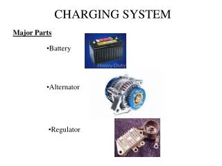
54 CHARGING SYSTEM
Figure 54-2 The end frame toward the drive belt is called the drive-end housing and the rear section is called the slip-ring-end housing.
Figure 54-4 An exploded view of an overrunning alternator pulley showing all of the internal parts.
TECH TIP: Alternator Horsepower and Engine Operation Many technicians are asked how much power certain accessories require. A 100 ampere alternator requires about 2 horsepower from the engine. One horsepower is equal to 746 watts. Watts are calculated by multiplying amperes times volts. Power in watts = 100 A × 14.5 V = 1,450 W 1 hp = 746 W Therefore, 1,450 watts is about 2 horsepower. Allowing about 20% for mechanical and electrical losses adds another 0.4 horsepower. Therefore, when someone asks how much power it takes to produce 100 amperes from an alternator, the answer is 2.4 horsepower.
FREQUENTLY ASKED QUESTION: Can I Install an OAP or an OAD to My Alternator? Usually, no. An alternator needs to be equipped with the proper shaft to allow the installation of an OAP or OAD. This also means that a conventional pulley often cannot be used to replace a defective overrunning alternator pulley or dampener with a conventional pulley. Check service information for the exact procedure to follow.
TECH TIP: Always Check the OAP or OAD First Overrunning alternator pulleys and overrunning alternator dampeners can fail. The most common factor is the one-way clutch. If it fails, it can freewheel and not power the alternator or it can lock up and not provide the dampening as designed. If the charging system is not working, the OAP or OAD could be the cause, rather than a fault in the alternator itself. In most cases, the entire alternator assembly will be replaced because each OAP or OAD is unique for each application and both require special tools to remove and replace. - SEE FIGURE 54–5.
Figure 54-5 A special tool is needed to remove and install overrunning alternator pulleys or dampeners.
Figure 54-6 A cutaway of an alternator, showing the rotor and cooling fan that is used to force air through the unit to remove the heat created when it is charging the battery and supplying electrical power for the vehicle
Figure 54-7 Rotor assembly of a typical alternator. Current through the slip rings causes the “fingers” of the rotor to become alternating north and south magnetic poles. As the rotor revolves, these magnetic lines of force induce a current in the stator windings.
Figure 54-8 An exploded view of a typical alternator showing all of its internal parts including the stator windings.
Figure 54-9 A rectifier usually includes six diodes in one assembly and is used to rectify AC voltage from the stator windings into DC voltage suitable for use by the battery and electrical devices in the vehicle.
Figure 54-10 Magnetic lines of force cutting across a conductor induce a voltage and current in the conductor.
Figure 54-11 A sine wave (shaped like the letter S on its side) voltage curve is created by one revolution of a winding as it rotates in a magnetic field.
Figure 54-12 When three windings (A, B, and C) are present in a stator, the resulting current generation is represented by the three sine waves. The voltages are 120 degrees out of phase. The connection of the individual phases produces a three-phase alternating voltage.
Figure 54-14 As the magnetic field, created in the rotor, cuts across the windings of the stator, a current is induced. Notice that the current path includes passing through one positive (+) diode on the way to the battery and one negative (-) diode as a complete circuit is completed through the rectifier and stator.
Figure 54-16 A stator assembly with six, rather than the normal three, windings.
Figure 54-18 A typical electronic voltage regulator with the cover removed showing the circuits inside.
Figure 54-19 Typical General Motors SI-style alternator with an integral voltage regulator. Voltage present at terminal 2 is used to reverse bias the zener diode (D2) that controls TR2. The positive brush is fed by the ignition current (terminal I) plus current from the diode trio.
Figure 54-20 A coolant-cooled alternator showing the hose connections where coolant from the engine flows through the rear frame of the alternator.
Figure 54-21 A Hall-effect current sensor attached to the positive battery cable is used as part of the EPM system.
Figure 54-22 The amount of time current is flowing through the field (rotor) determines the alternator output.
Chart 54-1 The output voltage is controlled by varying the duty cycle as controlled by the PCM.
TECH TIP: The Voltage Display Can Be a Customer Concern A customer may complain that the voltmeter reading on the dash fluctuates up and down. This may be normal as the computer-controlled charging system commands various modes of operation based on the operating conditions. Follow the vehicle manufacturer’s recommended procedures to verify proper operation.