1.4b Charging System
1.4b Charging System. Charging System. Function of the charging system. Convert mechanical energy into electrical energy Recharge battery Provide higher voltage than battery Change output to meet different electrical loads

1.4b Charging System
E N D
Presentation Transcript
Charging System Function of the charging system • Convert mechanical energy into electrical energy • Recharge battery • Provide higher voltage than battery • Change output to meet different electrical loads • Provide power for electrical accessories when the engine is running
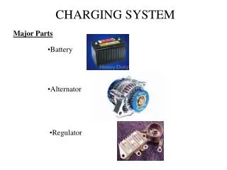
Charging System Main Components • Alternator • Drive belt • Voltage regulator • Charge indicator (lamp or gauge)
Charging System Main Components
Charging System • Ampere Usage
Charging System • Types of generators Magnetic Field Armature (Winding) • D.C generator Stationary Rotating • A.C generator Rotating Stationary
Charging System • Strength of current can increase by • Increasing the speed of the conductor passed through magnetic field • Increasing the number of conductors passing through the magnetic field • Increasing the strength of the magnetic field
Charging System • Alternator
The Charging System • The charging system has three major components. The Battery, Alternator, and the Regulator. • This alternator works together with the battery to supply power when the vehicle is running. • The output of an alternator is direct current, however AC voltage is actually created and then converted to DC as voltage leaves the alternator on its way to the battery and the electrical loads.
Charging System Circuit • Four wires connect the alternator to the rest of the charging system. • B is the alternator output wire that supplies current to the battery. • IG is the ignition input that turns on the alternator/regulator assembly. • S is used by the regulator to monitor charging voltage at the battery. • L is the wire the regulator uses to ground the charge warning lamp.
Alternator Terminal Identification “S” Terminal Senses Battery Voltage “L” Terminal Grounds Warning Lamp “F” Terminal Regulator Bypass Full Field Testing “B” Terminal Alternator Output Terminal to Battery “IG” Terminal Ignition Switch Signal Turns Regulator ON
Alternator Assembly Drive Frame Cover Identification Label End Frame Cover Drive Pulley Regulator, Diode, & Brush Cover Circulation Vent Alternator B+ Output Terminal Mounting Ear
Alternator Overview • The alternator contains: • A rotating field winding called the rotor. • A stationary induction winding called the stator. • A diode assembly called the rectifier bridge. • A control device called the voltage regulator. • Two internal fans to promote air circulation.
Alternator Design • Most regulators are on the inside the alternator. Older models have externally mounted regulators. • Unlike other manufacturers, this model can be easily serviced from the rear on the unit. • The rear cover can be removed to expose internal parts. • However, today’s practice is to correctly diagnose the problem and replace the alternator as a unit, should one of it’s internal components fail.
Drive Pulley • Alternator drive pulleys either bolt on or are pressed on the rotor shaft. • Both ‘V’ and Multi-grove types are used. • Note this alternator does not have an external fan as part of the pulley assembly. • While many manufacturers do use a external fan for cooling. This alternator has two internal fans to draw air in for cooling.
Inside the Alternator • Removal of the rear cover reveals: Regulator Brushes The Regulator controls the alternator output. The Brushes conduct current to the rotor field winding. The Rectifier Bridge converts AC voltage to DC voltage. Diode Rectifier Bridge Slip Rings (part of the Rotor Assembly)
Brushes • Two slip rings are located on one end of the rotor assembly. Each end of the rotor field winding is attached to a slip ring. Thereby, allowing current to flow through the field winding. • Two stationary carbon brushes ride on two rotating slip rings. Bushes are either soldered or bolted
Electronic IC Regulator • The regulator is the brain of the charging system. • It monitors both battery and stator voltages. Depending on the measured voltages, the regulator will adjust the amount of rotor field current to control alternator output. • Regulators can be mounted both internal or external. Current technology uses an internal regulator.
Diode Rectifier • The Diode Rectifier Bridge is responsible for for the conversion or rectification of AC voltage to DC voltage. • Six or eight diodes are used to rectify the AC stator voltage to DC voltage. • Half of these diodes are use on the positive side and the other half are on the negative side. • Further details about the rectifier bridge will be explained later.
Inside the Alternator • Separating the case reveals: The rotor winding assembly rotates inside the stator winding. The rotor generates a magnetic field. The stator winding develops voltage and current begins to flow from the induced magnetic field of the rotor. Rotor Winding Assembly Stator Winding
Rotor Assembly Internal Cooling Fan Finger Poles Rotor Field Winding Bearing InternalCooling Fan Rotor Shaft Slip Rings
Rotor Assembly • A basic rotor consists of a iron core, coil winding, two slip rings, and two claw-shaped finger pole pieces. • Some models include support bearings and one or two internal cooling fans. • The rotor is driven or rotated inside the alternator by an engine (alternator) drive belt.
Rotor Assembly • The rotor contains the field winding wound over an iron core which is part of the shaft. • Surrounding the field coil are two claw-type finger poles. • Each end of the rotor field winding is attached to a slip ring. Stationary brushes connect the alternator to the rotor. • The rotor assembly is supported by bearings. One on the shaft the other in the drive frame.
Alternating Magnetic Field • The rotor field winding creates the magnetic field that induces voltage into the stator. • The magnetic field is saturates the iron finger poles. One finger pole become a north pole and the other a south pole. • The rotor spins creating an alternating magnetic field, North, South, North, South, etc. North Field South Field North Field
Stator Winding StatorLead Ends Neutral Junction Laminated Iron Frame Three PhaseWindings
Rotor / Stator Relationship • As the rotor assembly rotates within the stator winding. • The alternating magnetic field from the spinning rotor induces an alternating voltage into the stator winding. • Both the strength of the magnetic field and the speed of the rotor affect the amount of voltage induced into the stator.
Stator Windings • The stator is made with three sets of windings. • Each winding is placed is a different position compared with the others. • A laminated iron frame concentrates the magnetic field. • Stator lead ends that output to the diode rectifier bridge. Stator Lead Ends Three Windings Laminated Iron Frame Neutral Junction in the Wye design can be identified by the 6 strands of wire
3 Phase Windings • The stator winding has three sets of windings. Each is formed into a number of evenly spaced coils around the stator core. • The result is three overlapping single phase AC sine wave current signatures, A, B, C. • Adding these waves together make up the total AC output of the stator. This is called three phase output current. • Three phase current provides a more constant current output.
Stator Design Delta wound stators can be identified by having only three stator leads, and each lead will have the same number of wires attached. Wye style has four stator leads. One of the leads is called the Neutral Junction. The Neutral Junction is common to all the other leads. Two designs of stator winding are used. Delta and Wye.
Wye Design Wye wound stators have three windings with a common neutral junction. They can be identified because they have 4 stator lead ends. Wye wound stators are used in alternators that require high voltage output a low alternator speed. Two windings are in series at any one time during charge output.
Delta Design Delta wound stators can be identified because they have only three stator lead ends. Delta stators allow for higher current flow being delivered at low RPM. The windings are in parallel rather than series as like the Wye design.
Diode Rectifier Bridge Assembly Negative Diodes Ground Points “B” Terminal “P” Terminal Stator Taps Attaches to Stator Windings Positive Diodes
Rectifier Operation • Two diodes are connected to each stator lead. One positive the other negative. • Because a single diode will only block half the the AC voltage. • Six or eight diodes are used to rectify the AC stator voltage to DC voltage. • Diodes used in this configuration will redirect both the positive and negative polarity signals of the AC voltage to produce DC voltage. This process is called ‘Full - Wave Rectification’. The Diode Rectifier Bridge is responsible for for the conversion or rectification the AC voltage into DC voltage.
Diodes • Diodes are used as one-way electrical check valves. Passing current in only one direction, never in reverse. • Diodes are mounted in a heat sink to dissipate the heat generated by the diodes. • Diodes redirect the AC voltage into DC voltage so the battery receives the correct polarity. Diodes
Rectifier Operation In red you can see B+ current pass through to the rectifier as it goes to the battery. In green you can see the return path. Now, in red B+ current passes through to the rectifier however, this time current has the opposite polarity. In green you can see the new return path. Even though it enters the rectifier at a different location, current goes to the battery in the same direction.
Electronic Regulator Heat Sink “S” Terminal Senses Battery Voltage “L” Terminal Warning Lamp “IG” Terminal Ignition Switch Signal Turns Regulator ON Regulator Ground “B” Terminal Connects to Alternator Output Terminal “P” Terminal Senses Neutral Junction voltage of Stator “F” Terminal Test Pad Full Field Test Point “F” Terminal Connects Regulatorto Rotor Winding
Voltage Regulation • The regulator will attempt to maintain a pre-determined charging system voltage level. • When charging system voltage falls below this point, the regulator will increase the field current, thus strengthening the magnetic field, which results in an increase of alternator output. • When charging system voltage raises above this point, the regulator will decrease field current , thus weakening the magnetic field, and results in a decrease of alternator output.
Regulator Types • Any one of two regulator designs can be used. • The Grounded Field type. The regulator controls the amount of B+ going to the field winding in the rotor. • The Grounded Regulator type. The regulator controls the amount battery ground (negative) going to the field winding in the rotor.
Working Alternator The regulator monitors battery voltage. Regulator The regulator controls current flow to the rotor assembly. The rotor produces a magnetic field. Voltage is induced into the stator. The rectifier bridge converts AC stator voltage to DC output for use by the vehicle. Diode Rectifier Bridge Contains the Rotor & Stator Slip Rings (part of the Rotor Assembly)