Chapter 6 DC Machines
Chapter 6 DC Machines. EET103/4. Introduction. An electrical machine is link between an electrical system and a mechanical system. Conversion from mechanical to electrical: generator Conversion from electrical to mechanical: motor. Introduction. Machines are called

Chapter 6 DC Machines
E N D
Presentation Transcript
Chapter 6DC Machines EET103/4
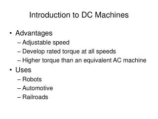
Introduction • An electrical machine is link between an electrical system and a mechanical system. • Conversion from mechanical to electrical: generator • Conversion from electrical to mechanical: motor
Introduction Machines are called • AC machines (generators or motors) if the electrical system is AC. • DC machines (generators or motors) if the electrical system is DC.
DC Machines Construction cutaway view of a dc machine
DC Machines Construction cutaway view of a dc machine
DC Machines Construction Rotor of a dc machine
DC Machines Construction Stator of a dc machine
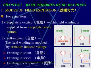
DC Machines Fundamentals • Stator: is the stationary part of the machine. The stator carries a field winding that is used to produce the required magnetic field by DC excitation. • Rotor (Armature): is the rotating part of the machine. The rotor carries a distributed winding, and is the winding where the e.m.f. is induced. • Field winding: Is wound on the stator poles to produce magnetic field (flux) in the air gap. • Armature winding: Is composed of coils placed in the armature slots. • Commutator: Is composed of copper bars, insulated from each other. The armature winding is connected to the commutator. • Brush: Is placed against the commutator surface. Brush is used to connect the armature winding to external circuit through commutator
DC Machines Fundamentals In DC machines, conversion of energy from electrical to mechanical form or vice versa results from the following two electromagnetic phenomena • When a conductor moves in a magnetic field, voltage is induced in the conductor. 2. When a current carrying conductor is placed in magnetic field, the conductor experiences a mechanical forces.
DC Machines Fundamentals Generator action: An e.m.f. (voltage) is induced in a conductor if it moves through a magnetic field. Motor action: A force is induced in a conductor that has a current going through it and placed in a magnetic field • Any DC machine can act either as a generator or as a motor.
DC Machines Equivalent Circuit The equivalent circuit of DC machines has two components: Armature circuit: • It can be represented by a voltage source and a resistance connected in series (the armature resistance). The armature winding has a resistance, RA. The field circuit: • It is represented by a winding that generates the magnetic field and a resistance connected in series. The field winding has resistance RF.
Basic Operation of DC Motor • In a dc motor, the stator poles are supplied by dc excitation current, which produces a dc magnetic field. • The rotor is supplied by dc current through the brushes, commutator and coils. • The interaction of the magnetic field and rotor current generates a force that drives the motor.
Basic Operation of DC Motor • The magnetic field lines enter into the rotor from the north pole (N) and exit toward the south pole (S) • The poles generate a magnetic field that is perpendicular to the current carrying conductors • The interaction between the field and the current produces a Lorentz force • The force is perpendicular to both the magnetic field and conductor
Basic Operation of DC Motor • The generated force turns the rotor until the coil reaches the neutral point between the poles. • At this point, the magnetic field becomes practically zero together with the force. • However, inertia drives the motor beyond the neutral zone where the direction of the magnetic field reverses. • To avoid the reversal of the force direction, the commutator changes the current direction, which maintains the counter clockwise rotation.
Basic Operation of DC Motor • Before reaching the neutral zone, the current enters in segment 1 and exits from segment 2 • Therefore, current enters the coil end at slot ‘a’ and exits from slot ‘b’ during this stage • After passing the neutral zone, the current enters segment 2 and exits from segment 1, • This reverses the current direction through the rotor coil, when the coil passes the neutral zone • The result of this current reversal is the maintenance of the rotation
Classification of DC Motor 1. Separately Excited DC Motor • Field and armature windings are either connected separate. 2. Shunt DC Motor • Field and armature windings are either connected in parallel. 3. Series DC Motor • Field and armature windings are connected in series. 4. Compound DC Motor • Has both shunt and series field so it combines features of series and shunt motors.
Important terms • VT– supply voltage • EA– internal generated voltage/back e.m.f. • RA – armature resistance • RF – field/shunt resistance • RS – series resistance • IL– load current • IF– field current • IA– armature current • IL– load current • n– speed
Generated or back e.m.f. of DC Motor • General form of back e.m.f., Φ = flux/pole (Weber) Z = total number of armature conductors = number of slots x number of conductor/slot P = number of poles A = number of parallel paths in armature [A = 2 (for wave winding), A = P (for lap winding)] N = armature rotation (rpm) EA = back e.m.f.
Torque Equation of a DC Motor • The armature torque of a DC motor is given by Φ = flux/pole (Weber) Z = total number of armature conductors = number of slots x number of conductor/slot P = number of poles A = number of parallel paths in armature IA = armature current Ta = armature torque
Equivalent Circuit of DC Motor Separately Excited DC Motor Shunt DC Motor
Series DC Motor Compound DC Motor
Speed of a DC Motor • For shunt motor • For series motor
Example 1 A 250 V, DC shunt motor takes a line current of 20 A. Resistance of shunt field winding is 200 Ω and resistance of the armature is 0.3 Ω. Find the armature current, IA and the back e.m.f., EA.
Solution Given quantities: • Terminal voltage, VT = 250 V • Field resistance, RF = 200 Ω • Armature resistance, RA = 0.3 Ω • Line current, IL = 20 A Figure 1
Solution (cont..) the field current, the armature current, VT = EA + IARA the back e.m.f., EA = VT – IARA = 250 V – (18.75)(0.3) = 244.375 V
Example 2 A 50hp, 250 V, 1200 r/min dc shunt motor with compensating windings has an armature resistance (including the brushes, compensating windings, and interpoles) of 0.06 Ω. Its field circuit has a total resistance Radj + RF of 50 Ω, which produces a no-load speed of 1200 r/min. There are 1200 turns per pole on the shunt field winding.
Example 2 (cont..) • Find the speed of this motor when its input current is 100 A. • Find the speed of this motor when its input current is 200 A. • Find the speed of this motor when its input current is 300 A.
Solution Given quantities: • Terminal voltage, VT = 250 V • Field resistance, RF = 50 Ω • Armature resistance, RA = 0.06 Ω • Initial speed, n1= 1200 r/min Figure 2
Solution (cont..) (a) When the input current is 100A, the armature current in the motor is Therefore, EA at the load will be
Solution(cont..) • The resulting speed of this motor is
Solution(cont..) (b) When the input current is 200A, the armature current in the motor is Therefore, EA at the load will be
Solution(cont..) • The resulting speed of this motor is
Solution (cont..) (c) When the input current is 300A, the armature current in the motor is Therefore, EA at the load will be
Solution (cont..) • The resulting speed of this motor is
Example 3 The motor in Example 2 is now connected in separately excited circuit as shown in Figure 3. The motor is initially running at speed, n = 1103 r/min with VA= 250 V and IA = 120 A, while supplying a constant-torque load. If VA is reduced to 200 V, determine i). the internal generated voltage, EA ii). the final speed of this motor, n2
Example 3 (cont..) Figure 3
Solution Given quantities • Initial line current, IL = IA = 120 A • Initial armature voltage, VA = 250 V • Armature resistance, RA = 0.06 Ω • Initial speed, n1 = 1103 r/min
Solution (cont..) i) The internal generated voltage EA= VT - IARA = 250 V – (120 A)(0.06 Ω) = 250 V – 7.2 V = 242.8 V
Solution (cont..) ii) Use KVL to find EA2 EA2= VT - IA2RA Since the torque is constant ant he flux is constant, IA is constant. This yields a voltage of EA2 = 200 V – (120 A)(0.06 Ω) = 200 V – 7.2 V = 192.8 V
Solution (cont..) • The final speed of this motor
Example 4 A DC series motor is running with a speed of 800 r/min while taking a current of 20 A from the supply. If the load is changed such that the current drawn by the motor is increased to 50 A, calculate the speed of the motor on new load. The armature and series field winding resistances are 0.2 Ω and 0.3 Ω respectively. Assume the flux produced is proportional to the current. Assume supply voltage as 250 V.
Solution Given quantities • Supply voltage, VT = 250 V • Armature resistance, RA = 0.2 Ω • Series resistance, RS = 0.3 Ω • Initial speed, n1= 800 r/min • Initial armature current, Ia1 =IL1 = 20 A Figure 4
Solution (cont..) For initial load, the armature current, Ia1 = 20 A and the speed n1= 800 r/min V = EA1 + Ia1 (RA + RS) The back e.m.f. at initial speed EA1 = V - Ia1 (RA + RS) = 250 – 20(0.2 + 0.3) = 240 V
Solution (cont..) When the armature current increased, Ia2 = 50 A, the back emf EA2 = V – Ia2 (RA + RS) = 250 – 50(0.2 + 0.3) = 225 V The speed of the motor on new load
Generating of an AC Voltage • The voltage generated in any dc generator inherently alternating and only becomes dc after it has been rectified by the commutator