Download
1 / 7
80 likes | 231 Vues
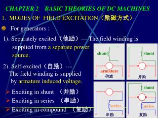
shunt. shunt. shunt. series. series. armature. 他励. 并励. 复励. 串励. CHAPTER 2 BASIC THEORIES OF DC MACHINES. 1. MODES OF FIELD EXCITATION (励磁方式). For generators :. 1). Separately excited (他励) --- The field winding is supplied from a separate power source.

E N D
shunt shunt shunt series series armature 他励 并励 复励 串励 CHAPTER 2 BASIC THEORIES OF DC MACHINES 1. MODES OF FIELD EXCITATION(励磁方式) • For generators : 1). Separately excited(他励)--- The field winding is supplied from a separate power source. 2). Self-excited(自励)--- The field winding is supplied by armature induced voltage. • Exciting in shunt (并励) • Exciting in series (串励) • Exciting in compound (复励)
shunt shunt shunt series series armature 他励 并励 复励 串励 • For motors : Both field windings and armature winding are • supplied with external supplies. • Exciting in shunt (并励) • Exciting in series (串励) • Exciting in compound (复励) • Separately excited(他励) • Note: • Generators and motors have different referring directions. • Shunt field winding has large turns but smaller current. • Series field winding is contrary to shunt one.
2. ARMATURE REACTION (电枢反应) 1). Main Flux and Main Magnetic Circuit Main flux ---passing through airgap and linking with both stator and rotor. Main magnetic circuit --- the path that main flux flows through. 8 parts--- 2 main poles, 2 airgap, 2 rotor teeth, 1 rotor core and 1 stator york. Note: (i). Since the reluctance in airgap is much greater than the other parts, we can assume that the total mmf’s fall down on the airgap. (ii). As armature conductors are in the Airgap field, we will just pay our attention to the airgap fieldand discuss its features.
Mmf distribution is a • rectangular wave. • Flux density distribution is • similar to mmf, except in the • interpolar region where there • are some slopes due to large • reluctance. 2). No-load Airgap Field At no-load, armature current Ia=0. Airgap field is established only by the exciting current of field windings .
Mmf distribution is a triangular wave. From Ampere’s Law, Draw a closed path and the mmf acting on the path is --- electric load(电负荷) 3). Airgap Field at Load At load, armature current is not zero. The airgap field is excited by both the field windings and armature winding. • airgap field established only by armature current I --- conductor current N --- number of conductors D --- armature diameter
For each air gap, 2). At --- pole pitch 3). The is at the point where the direction of current is changed. Features: 1). Triangular wave • Distribution of armature flux density Ba is a saddle curve --- Having a dip in interpolar region due to large reluctance
Armature Reaction Definition : The effects of armature mmf to the no-load field is referred to as armature reaction. (1). Making airgap field distortion --- making flux density increase under one half of the pole and decrease under the other half (2). Producing demagnetizing effect if saturation occurs. --- If saturation occurs, the flux per pole will be decreased (3). Making the zero flux density point departure from q-axis --- leading to poor commutation Compensating winding (补偿绕组) • Be mounted on the main pole face and connected in series with armature winding. • The mmf produced opposes the armature mmf.