Download
1 / 57
600 likes | 997 Vues
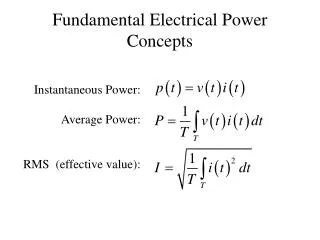
Fundamental of Electrical Engineering. Fundamental of Electrical Engineering EMT 113/4. Semester II 09/10. CHAPTER 1: TRANSFORMER. Fundamental of Electrical Engineering. Electrical Machines. Device that can convert either mechanical energy to electrical energy or vice versa.

E N D
Fundamental of Electrical Engineering Fundamental of Electrical EngineeringEMT 113/4 Semester II 09/10 CHAPTER 1: TRANSFORMER
Fundamental of Electrical Engineering Electrical Machines Device that can convert either mechanical energy to electrical energy or vice versa. Semester II 09/10 TRANSFORMER: Device that changes ac electric energy at one voltage level to ac electric energy at another voltage level through the action of magnetic field.
Fundamental of Electrical Engineering WHY NEED TRANSFORMER ?? • Power efficiency over a long distance • Power at high voltage is necessary to decrease the lines losses. • Power at low voltage is necessary to be used at safe level in home appliances and most equipments. • Principal purpose: convert ac power at one voltage • level to ac power of the same frequency at another • voltage level. Semester II 09/10
Fundamental of Electrical Engineering Construction Semester II 09/10 • 1. The primary winding -the input winding, connected to an ac power source • 2. The secondary winding is the output winding. • 3. The windings are not directly connected. Magnetic flux present in ferromagnetic core connects the windings.
TYPES OF TRANSFORMER CORE SHELL TYPES OF TRANSFORMER Fundamental of Electrical Engineering Windings wrapped around the two sides of a rectangular laminated piece of steel. Semester II 09/10 Windings wrapped around the center leg of a three-legged laminated core. ** both core is built up of thin laminations, which are electrically isolated from each other to minimize eddy currents
Fundamental of Electrical Engineering Transformer : Operation Semester II 09/10 • AC voltage is applied to the primary winding (N1), result an AC current. • The AC primary current i1sets up a time-varying magnetic flux φ in the core. The flux links the secondary winding(N2) of the transformer. • Flux in the core induce electromagnetic forces (EMF) in N1 and N2 due to a time rate of change of φM (mutual flux), as stated by the Faraday’s Law.
…………………………(1.2) Fundamental of Electrical Engineering Faraday’s Law: - Show that voltage,e is generated by a coil of wire when magnetic flux in circuit changes for any reason Semester II 09/10 • Where, • e : instantaneous voltage induced by magnetic field (emf) • : number of flux linkages between the magnetic field and the electric circuit. • : effective flux
………………………………(1.3) Fundamental of Electrical Engineering • The voltage induced in the primary is nearly equal to the applied voltage, and the voltage at the secondary winding also differs by only a few percent from the voltage induced into that winding. • Thus, the primary-to-secondary voltage ratio is essentially equal to the ratio of the number of turn in the two windings. Turn ratio, a: Semester II 08/09 Semester II 09/10 • According to Faraday’s law, the voltage induced is proportional to • the number of the turn in the windings, thus • and ………......……..(1.4)
…........…..(1.5) Fundamental of Electrical Engineering • If the resistance is neglected, equation (1.2) becomes. Semester II 09/10 • By neglecting the power losses, • Power in primary winding = Power in secondary winding
…………......…….(1.7) ………………….(1.8) Fundamental of Electrical Engineering Substituting equation 1.1 into equation 1.4 Semester II 09/10 Solve for this equation …then the rms value of the induced voltage is given as f = frequency in hertz ; also known as the emf equation
……………………………..............................(1.9)……………………………..............................(1.9) Fundamental of Electrical Engineering Combine equations 1.3; 1.4;1.5 and 1.6, Turn ratio, a will classify the transformer : Semester II 09/10 If, a > 1 Step down transformer a < 1 Step up transformer a = 1 Isolation Transformer
Fundamental of Electrical Engineering TRANSFORMER CLASSIFICATIONS: Step-uptransformers • Permit higher voltage at secondary windings • connected between the generator and transmission line. • Turn ratio, a < 1 • Step-downtransformers • connected between the transmission line and various electrical loads. • Permit low voltage at secondary windings • Turn ratio, a > 1 Semester II 09/10
Fundamental of Electrical Engineering • TRANSFORMER POLARITY - DOT CONVENTION: • The dot convention appearing at one end of each winding tell the polarityof the voltage and current on the secondary side of the transformer. • If the primary voltage is positive at the dotted end of the winding with respect to the undotted end, then the secondary voltage will be positive at the dotted end also. Voltage polarities are the same with respect to the doted on each side of the core. • If the primary current of the transformer flow intothe dotted end of the primary winding, the secondary current will flow outof the dotted end of the secondary winding. Semester II 09/10
Fundamental of Electrical Engineering Theory of Transformer : Operation Semester II 09/10
v1=e1 v2=e2 Fundamental of Electrical Engineering Ideal Transformer • Characteristics of an ideal transformer • - Windings with zero impedance • - Lossless • - Infinite permeability core • - 100% efficiency Semester II 09/10 • Zero resistance result in zero voltage drops between the terminal voltages and induced voltages • In term of phasor quantities (or rms value), these quantities are
Fundamental of Electrical Engineering • The power supplied to the transformer by the primary winding: • Where: • cos = power factor • 1= the angle between the primary voltage and the primary current • The power supplied by the transformer secondary winding: • Where: • 2= the angle between the secondary voltage and the secondary current • For an ideal transformer, 1=2 ;same power factor, then Pin = V1I1 cos 1 Semester II 09/10 Pout = V2I2 cos 2 Pout = Pin
Fundamental of Electrical Engineering Same with Q and S: The reactive power (Q) The apparent (complex) power (S) Qout = Qin = V1I1 sin = V2I2 sin (VAR) Semester II 09/10 Sout = Sin = V1I1 = V2I2(VA)
Fundamental of Electrical Engineering S = VI = P ± jQ S = Apparent power, unit=VA. P = Average power (also known as real power) , unit = Watt Q = Reactive power, unit=VAR Power factor also = ratio between real power and complex power = P/S Semester II 09/10
Fundamental of Electrical Engineering Ideal Transformer : Impedance Impedance - the ratio of the phasor voltage across it to the phasor current flowing through it. Semester II 09/10 Impedance of primary circuit Figure: a) Definition of Impedance; b) Impedance through transformer
Fundamental of Electrical Engineering Non Ideal Transformer • Two components of flux exist: • leakage flux - flux links only the primary or secondary winding. • mutual flux - links both primary and secondary windings Semester II 09/10 • For a non-ideal/practical transformer, the output power is less than the input power because of losses. • Practical transformer has : • Hysteresis losses • Eddy-current (or core) losses • Leakage flux losses • Resistive losses • In primary and secondary windings
Fundamental of Electrical Engineering Non Ideal Transformer • LOSSES IN TRANSFORMER: • Copper losses – The resistive heating losses in the primary and secondary windings • Eddy Current Losses - The resistive heating losses in the core of the transformer • Hysteresis losses - Associated with the re-arrangement of the magnetic domains in the core during each half cycle. They are complex, nonlinear function of the voltage applied to the transformer. • Leakage flux – the fluxes at primary and secondary which escape the core and pass through only one of the transformer windings. • These losses that occurred in real transformers are modeled in the • transformer model • - Exact Equivalent model • - Approximate model Semester II 09/10
No-Load Fundamental of Electrical Engineering Non Ideal Transformer NO LOAD Semester II 09/10 Power out = 0 (no load at secondary ) Power in = power out + power loss Power loss = core loss + Cu loss Cu = 0 (no load) Power in = core loss =Ic2Rc Watt
Fundamental of Electrical Engineering Non Ideal Transformer UNDER LOAD Semester II 09/10
Fundamental of Electrical Engineering The previous figures are accurate model of a transformer, but to analyze practical circuits containing transformer, it is necessary to refer to its primary side or to its secondary side because it is necessary to convert the entire circuit to an equivalent circuit at asingle voltage level. Semester II 09/10
Fundamental of Electrical Engineering EQUIVALENT CIRCUIT Referred to primary Semester II 09/10 Referred to secondary
I2/a Fundamental of Electrical Engineering Non Ideal Transformer APPROXIMATE EQUIVALENT CIRCUIT Referred to primary Semester II 09/10 Req_1 = R1 + a2R2 jXeq_1 = X1 + a2X2
Fundamental of Electrical Engineering Non Ideal Transformer APPROXIMATE EQUIVALENT CIRCUIT Referred to secondary Semester II 09/10 Req_2 = R1/a2 + R2 jXeq_2 = X1/a2 + X2
Fundamental of Electrical Engineering Non Ideal Transformer APPROXIMATE EQUIVALENT CIRCUIT In some applications, the excitation branch may be neglected entirely without causing error. In this cases, the equivalent circuits in the previous slides reduces to these simples circuits: Referred to secondary Referred to primary Semester II 09/10
Fundamental of Electrical Engineering Transformer Characteristics • Transformer characteristics can be defined by:- • Efficiency • Voltage regulation. • Good transformers has high efficiency and low voltage regulation. • Through short circuit and open circuit test, parameter, power loss, efficiency and voltage regulation can be determined Semester II 09/10
Fundamental of Electrical Engineering Transformer Efficiency Efficiency of a transformer is defined as : In practice, the efficiency of a transformer is about 97% or better Semester II 09/10 For a non-ideal transformer, the output power is less than the input power because of losses. 2 types of losses – Copper losses (winding or I2R losses) - Core losses (Hysteresis & eddy-current losses )
Fundamental of Electrical Engineering Ideally, For non-ideal transformer, losses are considered, therefore Semester II 09/10 Then,
Fundamental of Electrical Engineering Transformer Voltage Regulation • Voltage regulation - a measure of the change in the terminal voltage of the transformer with respect to loading. • Defined as • V.R Semester II 09/10 In calculation of voltage regulation, the equivalent circuit can be referred to primary and secondary side. Good practice to have a small voltage regulation as possible. For an ideal transformer, V.R = 0 %
Fundamental of Electrical Engineering Open Circuit Test • In open Circuit Test: • one winding of the transformer is open while the other is excited by applying rated voltage • Test is conducted on the low voltage, LV side of the transformer (power, voltage and current are measured from LV side) • It means that voltage is applied at low voltage, LV side while the high voltage, HV side is opened Semester II 09/10
2 2 2 Fundamental of Electrical Engineering Open Circuit Test Open circuit test : Need to determine RcLV & XmLV Semester II 09/10
Fundamental of Electrical Engineering Short Circuit Test • This test is designed to determine the winding resistances and leakage resistance • In short circuit test: • one winding of the transformer is short while another winding is excited by applying rated voltage • test is conducted on high voltage, HV side with short circuit on the low voltage, LV side Semester II 09/10
Fundamental of Electrical Engineering Short Circuit Test Short circuit test : Need to determine ReHV & XeHV 2 2 Semester II 09/10
Fundamental of Electrical Engineering Simplified Circuit Simplified Circuit referred to HV (primary) Simplified Circuit referred to LV (secondary) Semester II 09/10
Fundamental of Electrical Engineering Transformer Phasor Diagram • What is phasor diagram? • A sketch of phasor voltages and currents in the transformer. • Why need it? • Easiest way to determine the effect of the impedances and the current phase angles on the transformer voltage regulation. • Vs is assumed to be at an angle of 0 degree, and all other voltages and currents are compared to that references. • A transformer phasor diagram is presented by applying Kirchhoff's Voltage law to the transformer equivalent circuit and an equation will be as follows. Semester II 09/10
Lagging Power Factor Unity Power Factor Leading Power Factor Fundamental of Electrical Engineering Transformer Phasor Diagram Semester II 09/10
Fundamental of Electrical Engineering Transformer Application • Voltage level adjustment (step-up and step-down transformers). • Voltage and current measurement. • Isolation for safety (isolation transformers) • Impedance matching (for maximum power transfer from the source to the load) Semester II 09/10 • Review: • Unit transformer – Connected the output of a generator and used to step the voltage up to transmission levels (110kV) • Substation transformer – Connected at the other end of the transmission line which steps the voltage down from transmission level to distribution levels (2.3 to 34.5 kV). • Distribution transformer – Takes the distribution voltage and steps it down to the final voltage (110V, 208V,220V,etc) • Special-purpose transformers : • Potential transformer • Current transformer
Fundamental of Electrical Engineering Transformer Application Semester II 09/10 Elements of Power Transmission and Distribution System
Fundamental of Electrical Engineering Three Phase Transformer Almost all the major power generation and distribution systems in the world today are three-phase ac system. Two ways of constructing transformer of three-phase circuit; (i) Three single phase transformers are connected in three-phase bank. Semester II 09/10
Fundamental of Electrical Engineering Three Phase Transformer (ii) Make a three-phased transformer consisting of three sets of windings wrapped on a common core. The three-phased transformer on a common core is preferred because it is lighter, smaller, cheaper and slightly more efficient. Semester II 09/10
Fundamental of Electrical Engineering Three Phase Transformer • Advantages three phase transformer • Less material for the same three phase power and voltage ratings • Smaller/lighter because all connection are made internally • Less cost to manufacture • Less external wiring • It has slightly better efficiency • Disadvantages three phase transformer • Failure of one phase puts the entire transformer out of service. Semester II 09/10
Fundamental of Electrical Engineering Three Phase Transformer The primary and secondary windings of the three phase transformer may be independently connected in either a WYE (Y) or DELTA () connection. As a result, four types of three phase transformers are commonly use. Semester II 09/10
Fundamental of Electrical Engineering Example 1 1. A 250 kVA, 11000V/400V, 50Hz single phase transformer has 80 turns on the secondary. Assume the transformer is ideal. Calculate: a) The values of the primary and secondary currents b) The number of primary turns c) The maximum value of flux, фm. Semester II 09/10
Fundamental of Electrical Engineering Solution Example 1 SOLUTION: a) I1 = S1/V1 = 250kVA/11kV = 22.73A I2 = V1I1/V2 = (11kV)(22.73A) / 400V = 625 A b) a = N1/N2 = I2/I1 = V1/V2 a = V1/V2 = 11000V/400V = 27.5 N1 = aN2 = (27.5)(80) = 2200 turns c) E1 = 4.44 fN1 фmax E1 = V1 Фmax = V1/4.44 fN1 = 11000V / (4.44)(50Hz)(2200) = 22.5mWb Semester II 09/10
Fundamental of Electrical Engineering Example 2 2. A single phase power system consists of a 480-60Hz generator supplying a load Zload= 4 + j3Ω through a transmission line of impedance Zline = 0.18 + j0.24Ω. Answer the following question about the system. If the power is exactly as described in the Figure1, what will the voltage at the load be? What will the transmission line losses be? Semester II 09/10
Fundamental of Electrical Engineering Solution Example 2 Solution: IL = V/ (Zline + Zload) Zline + Zload = (0.18 + j0.24Ω) + (4 + j3Ω) = 4.18 + j3.24 = 5.29 < 37.8o IL = 480 < 0o / (5.29< 37.8o) = 90.74 < -37.8o A VLoad = IL x ZLoad = (90.74 < -37.8o) (5 < 36.9o) = 4537 < - 0.9o V Line Losses = ILine2 x RLinePower in Watt only consider Resistance = (90.74) 2 (0.18) = 1482 W Semester II 09/10
Fundamental of Electrical Engineering Example 3 3. Test are performed on a 1ф, 10 kVA, 2200/220V, 60 Hz transformer and the following results are obtained. Semester II 09/10 • Derive the parameters for the approximate equivalent circuits referred to the low voltage and high voltage side. • Express the excitation current as a percentage of the rated current • Determine the power factor for the no load and short circuit test