Understanding Spanning Tree Protocol (STP) for Network Stability
Discover how Spanning Tree Protocol (STP) prevents network loops, allows redundant links, and ensures resilience to failures. Learn about STP algorithm steps and port states.

Understanding Spanning Tree Protocol (STP) for Network Stability
E N D
Presentation Transcript
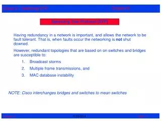
Introducing Spanning-Tree Protocol Broadcast Frame Standby Link • Switches forward broadcast frames • Prevents loops • Loops can cause broadcast storms, exponentially proliferate frames • Allows redundant links • Prunes topology to a minimal spanning tree • Resilient to topology changes and device failures • Main function of the Spanning Tree Protocol (STP) is to allow redundant switched/bridged paths without suffering the effects of loops in the network
The STA is used to calculate a loop-free path. • Spanning-tree frames called bridge protocol data units (BPDUs) are sent and received by all switches in the network at regular intervals and are used to determine the spanning tree topology. • A separate instance of STP runs within each configured VLAN. • (VLANs are later)
Understanding STP States States initially set, later modified by STP • Blocking • Listening • Learning • Forwarding • Disabled Server ports can be configured to immediately enter STP forward mode
Understanding STP States • Blocking - No frames forwarded, BPDUs heard • Listening - No frames forwarded, listening for frames • Learning - No frames forwarded, learning addresses • Forwarding - Frames forwarded, learning addresses • Disabled - No frames forwarded, no BPDUs heard
Spanning Tree Algorithm (STA) • Part of 802.1d standard • Simple principle: Build a loop-free tree from some identified point known as the root. • Redundant paths allowed, but only one active path. • Developed by Radia Perlman
Spanning Tree Process • Step 1: Electing a Root Bridge • Step 2: Electing Root Ports • Step 3: Electing Designated Ports • All switches send out Configuration Bridge Protocol Data Units (Configuration BPDU’s) • BPDU’s are sent out all interfaces every two seconds (by default - tunable) • All ports are in Blocking Mode during the initial Spanning Tree is process.
3 Switches with redundant paths Can you find them? Moe 1 A B 10BaseT Ports (12) 100BaseT Ports Larry A B 10BaseT Ports (24) 100BaseT Ports Curly A B 1 100BaseT Ports 10BaseT Ports (24)
3 Steps to Spanning Tree • Step 1: Electing a Root Bridge • Bridge Priority • Bridge ID • Root Bridge • Step 2: Electing Root Ports • Path Cost or Port Cost • Root Path Cost • Root Port • Step 3: Electing Designated Ports • Path Cost or Port Cost • Root Path Cost
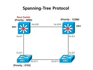
Step 1: Electing a Root Bridge • The first step is for switches to select a Root Bridge. • The root bridge is the bridge from which all other paths are decided. • Only one switch can be the root bridge. • Election of a root bridge is decided by: • 1. Lowest Bridge Priority • 2. Lowest Bridge ID (tie-breaker)
Bridge Priority • This is a numerical value. • The switch with the with the lowest bridge priority is the root bridge. • The switches use BPDU’s to accomplish this. • All switches consider themselves as the root bridge until they find out otherwise. • All Cisco Catalyst switches have the default Bridge priority of 32768. • It’s a tie! So then what?
Bridge Priorities Moe 1 A B 10BaseT Ports (12) 100BaseT Ports Larry A B 10BaseT Ports (24) 100BaseT Ports Curly A B 1 100BaseT Ports 10BaseT Ports (24)
In case of a tie, the Bridge ID is used… • Bridge ID • The Bridge ID is the MAC address assigned to the individual switch. • The lower Bridge ID (MAC address) is the tiebreaker. • Because MAC addresses are unique, this ensures that only one bridge will have the lowest value. • NOTE: There are other tie breakers, if these values are not unique, but we will not cover those situations.
Bridge Priorities and Bridge Ids Which one is the lowest? Moe 1 A B Priority: 32768 ID: 00-B0-64-26-6D-00 10BaseT Ports (12) 100BaseT Ports Larry A B Priority: 32768 ID: 00-B0-64-58-CB-80 10BaseT Ports (24) 100BaseT Ports Curly A B Priority: 32768 ID: 00-B0-64-58-DC-00 1 10BaseT Ports (24)
You got it! Lowest: Moe becomes the root bridge Moe 1 Priority: 32768 ID: 00-B0-64-26-6D-00 A B 10BaseT Ports (12) 100BaseT Ports Larry Priority: 32768 ID: 00-B0-64-58-CB-80 A B 10BaseT Ports (24) Curly Priority: 32768 ID: 00-B0-64-58-DC-00 1 A B 10BaseT Ports (24)
Step 2: Electing Root Ports • After the root bridge is selected, switches (bridges) must locate redundant paths to the root bridge and block all but one of these paths. • The switches use BPDU’s to accomplish this. • How does the switch make the decision on which port to use, known as the root port, and which one should be blocked?
Redundant Paths Moe 1 Priority: 32768 ID: 00-B0-64-26-6D-00 A B 10BaseT Ports (12) 100BaseT Ports Larry Priority: 32768 ID: 00-B0-64-58-CB-80 A B ? 10BaseT Ports (24) ? 100BaseT Ports Curly Priority: 32768 ID: 00-B0-64-58-DC-00 ? 1 100BaseT Ports 10BaseT Ports (24) ? A B
Path Cost (or Port Cost) • Port Cost is used to help find the “cheapest” or “fastest” path to the root bridge. • By default, port cost is usually based on the medium or bandwidth of the port. • On Cisco Catalyst switches, this value is derived by dividing 1000 by the speed of the media in megabits per second. • Examples: • Standard Ethernet: 1,000/10 = 100 • Fast Ethernet: 1,000/100 = 10
Root Path Cost • The root path cost is the cumulative port costs (path costs) to the Root Bridge. • This value is transmitted in the BPDU cost field.
However, everything is viewed in relation to the root bridge. • Root Ports • Ports directly connected to the root bridge will be the root ports. • Otherwise, the port with the lowest root path cost will be the root port.
Path Costs Moe 1 Priority: 32768 ID: 00-B0-64-26-6D-00 A B 10BaseT Ports (12) 100BaseT Ports Larry Priority: 32768 ID: 00-B0-64-58-CB-80 A B 10 10 10BaseT Ports (24) 100BaseT Ports Curly Priority: 32768 ID: 00-B0-64-58-DC-00 10 1 100BaseT Ports 10BaseT Ports (24) 100 A B
Curly • Even though the Path Cost to the root bridge for Curly is higher using Port 1, Port 1 has a direct connection to the root bridge, thus it becomes the root port. • Port 1 is then put in Forwarding mode, while the redundant path of Port A, is put into Blocking mode.
Curly Moe 1 Priority: 32768 ID: 00-B0-64-26-6D-00 A B 10BaseT Ports (12) 100BaseT Ports Larry Priority: 32768 ID: 00-B0-64-58-CB-80 A B 10BaseT Ports (24) 100BaseT Ports Curly X Blocking Priority: 32768 ID: 00-B0-64-58-DC-00 1 100BaseT Ports Forwarding 10BaseT Ports (24) A B
Larry • Larry also has a root port, a direct connection with the root bridge, through Port B. • Port B is then put in Forwarding mode, while the redundant path of Port A, is put into Blocking mode.
Larry Moe 1 A B Priority: 32768 ID: 00-B0-64-26-6D-00 10BaseT Ports (12) 100BaseT Ports Forwarding Larry Priority: 32768 ID: 00-B0-64-58-CB-80 A B 100BaseT Ports 10BaseT Ports (24) X Blocking Curly X Blocking Priority: 32768 ID: 00-B0-64-58-DC-00 1 100BaseT Ports Forwarding 10BaseT Ports (24) A B
Root Ports Moe 1 A B Priority: 32768 ID: 00-B0-64-26-6D-00 10BaseT Ports (12) 100BaseT Ports Larry Priority: 32768 ID: 00-B0-64-58-CB-80 Root Port A B 100BaseT Ports 10BaseT Ports (24) X Blocking Curly X Blocking Priority: 32768 ID: 00-B0-64-58-DC-00 1 Root Port 100BaseT Ports 10BaseT Ports (24) A B
Step 3: Electing Designated Ports • The single port for a switch that sends and receives traffic to and from the Root Bridge. • It can also be thought of as the port that is advertising the lowest cost to the Root Bridge. • In our example, we only have the two obvious choices, which are on switch Moe. • If we had other LAN segments, we could explain designated ports in more detail, but this is fine for now.
Designated Ports Moe 1 A B Priority: 32768 ID: 00-B0-64-26-6D-00 Designated Port Designated Port 10BaseT Ports (12) Forwarding Larry Priority: 32768 ID: 00-B0-64-58-CB-80 A B 100BaseT Ports 10BaseT Ports (24) X Blocking Curly X Blocking Priority: 32768 ID: 00-B0-64-58-DC-00 1 100BaseT Ports Forwarding 10BaseT Ports (24) A B
Spanning Tree is now complete, and the switches can begin to properly switch frames out the proper ports with the correct switching tables and without creating duplicate frames.
Most LAN and switched internetwork books provide information on Spanning Tree. For more complex examples, you may wish to try these books: • Cisco Catalyst LAN Switching, by Rossi and Rossi, McGraw Hill (Very Readable) • CCIE Professional Development: Cisco LAN Switching, by Clark and Hamilton, Cisco Press (More Advanced) • Interconnections, by Radia Perlman, Addison Wesley (Excellent, but very academic)
Extra Item! • Port Fast Mode (from Cisco documentation) • Port Fast modeimmediately brings a port from the blocking state into the forwarding state by eliminating the forward delay (the amount of time a port waits before changing from its STP learning and listening states to the forwarding state).
When the switch is powered up, the forwarding state, even if Port Fast mode is enabled, is delayed to allow the Spanning-Tree Protocol to discover the topology of the network and ensure no temporary loops are formed. • Spanning-tree discovery takes approximately 30 seconds to complete, and no packet forwarding takes place during this time. • After the initial discovery, Port Fast-enabled ports transition directly from the blocking state to the forwarding state.
Spanning Tree Completed Moe 1 A B Priority: 32768 ID: 00-B0-64-26-6D-00 10BaseT Ports (12) 100BaseT Ports Forwarding Larry Priority: 32768 ID: 00-B0-64-58-CB-80 A B 100BaseT Ports 10BaseT Ports (24) X Blocking Curly X Blocking Priority: 32768 ID: 00-B0-64-58-DC-00 1 100BaseT Ports Forwarding 10BaseT Ports (24) A B
The Spanning Tree Algorhymeby Radia Perlman I think that I shall never see A graph more lovely than a tree. A tree whose crucial property Is loop-free connectivity. A tree that must be sure to span. So packets can reach every LAN. First , the root must be selected. By ID, it is elected. Least cost paths from root are traced. In the tree, these paths are placed. A mesh is made by folks like me, Then bridges find a spanning tree.