Spanning Tree Protocol (STP)
Spanning Tree Protocol (STP). W.lilakiatsakun. Redundancy (1). Redundancy (2). Redundancy (3). Examine Redundancy (1). Examine Redundancy (2). Examine Redundancy (3). Examine Redundancy (4). Examine Redundancy (5). Issues with Redundancy- layer2 loop (1). LAYER 2 Loop

Spanning Tree Protocol (STP)
E N D
Presentation Transcript
Spanning Tree Protocol (STP) W.lilakiatsakun
Issues with Redundancy- layer2 loop (1) • LAYER 2 Loop • Ethernet framesdo not have a time to live (TTL) like IP packets traversing routers. As a result, if they are not terminated properly on a switched network, they continue to bounce from switch to switch endlessly or until a link is disrupted and breaks the loop. Broadcast frames are forwarded out all switch ports, except the originating port. • This ensures that all devices in the broadcast domain are able to receive the frame. • If there is more than one path for the frame to be forwarded out, it can result in an endless loop.
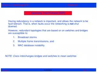
Issues with Redundancy – broadcast storm (1) • Broadcast storm • A broadcast storm occurs when there are so many broadcast frames caught in a Layer 2 loop that all available bandwidth is consumed. • Consequently, no bandwidth is available bandwidth for legitimate traffic, and the network becomes unavailable for data communication.
Issues with Redundancy – Duplicate Unicast frame (1) • Duplicate Unicast Frames • Broadcast frames are not the only type of frames that are affected by loops. • Unicast frames sent onto a looped network can result in duplicate frames arriving at the destination device.
Real world Redundancy issues - Loops in the Wiring Closet(1) • Loops in the Wiring Closet • Network cables between access layer switches, located in the wiring closets, disappear into the walls, floors, and ceilings where they are run back to the distribution layer switches on the network. • If the network cables are not properly labeled when they are terminated in the patch panel in the wiring closet, it is difficult to determine where the destination is for the patch panel port on the network. • Network loops that are a result of accidental duplicate connections in the wiring closets are a common occurrence.
Real world Redundancy issues - Loops in the Wiring Closet(2)
Real world Redundancy issues - Loops in the Wiring Closet(3)
Real world Redundancy issues - Loops in the Cubicles (1) • Loops in the Cubicles • Wiring closets are typically secured to prevent unauthorized access, so often the network administrator is the only one who has full control over how and what devices are connected to the network. • Unlike the wiring closet, the administrator is not in control of how personal hubs and switches are being used or connected, so the end user can accidentally interconnect the switches or hubs.
STP Topology (1) • STP ensures that there is only one logical path between all destinations on the network by intentionally blocking redundant paths that could cause a loop. • Blocking the redundant paths is critical to preventing loops on the network. • The physical paths still exist to provide redundancy, but these paths are disabled to prevent the loops from occurring. • If the path is ever needed to compensate for a network cable or switch failure, STP recalculates the paths and unblocks the necessary ports to allow the redundant path to become active.
STP Algorithm (1) • STP uses the Spanning Tree Algorithm (STA) to determine which switch ports on a network need to be configured for blocking to prevent loops from occurring. • The STA designates a single switch as the root bridge and uses it as the reference point for all path calculations. • All switches participating in STP exchange BPDU frames to determine which switch has the lowest bridge ID (BID) on the network. • The switch with the lowest BID automatically becomes the root bridge for the STA calculations.
STP Algorithm (2) • After the root bridge is selected, the STA calculates the shortest path to the root bridge. • Each switch uses the STA to determine which ports to block. • The STA considers both path and port costs when determining which path to leave unblocked. • The path costs are calculated using port cost valuesassociated withport speeds for each switch port along a given path. • The sum of the port cost values determines the overall path cost to the root bridge. • If there is more than one path to choose from, STA chooses the path with the lowest path cost.
STP Algorithm (3) • Root ports - Switch ports closest to the root bridge.
STP Algorithm (4) • Designated ports - All non-root ports that are still permitted to forward traffic on the network.
STP Algorithm (5) • Non-designated ports - All ports configured to be in a blocking state to prevent loops.
Selecting The root bridge (1) • The Root Bridge • Every spanning-tree instance (switched LAN or broadcast domain) has a switch designated as the root bridge. • The root bridge serves as a reference point for all spanning-tree calculations to determine which redundant paths to block.
Selecting The root bridge (2) • After a switch boots, it sends out BPDU frames containing the switch BID and the root ID every 2 seconds. • By default, the root ID matches the local BID for all switches on the network. • The root ID identifies the root bridge on the network. • Initially, each switch identifies itself as the root bridge after bootup.
Selecting The root bridge (3) • If the root ID from the BPDU received is lower than the root ID on the receiving switch, the receiving switch updates its root ID identifying the adjacent switch as the root bridge. • Eventually, the switch with the lowest BID ends up being identified as the root bridge for the spanning-tree instance.
Best Path to the root bridge (1) • The path information is determined by summing up the individual port costs along the path from the destination to the root bridge. • The default port costs are defined by the speed at which the port operates. • 10-Gb/s Ethernet ports have a port cost of 2, • 1-Gb/s Ethernet ports have a port cost of 4, • 100-Mb/s Fast Ethernet ports have a port cost of 19, • 10-Mb/s Ethernet ports have a port cost of 100.
Best Path to the root bridge (2) • Default port cost
BPDU Process (1) • Each switch in the broadcast domain initially assumes that it is the root bridge for the spanning-tree instance, so the BPDU frames sent contain the BID of the local switch as the root ID. • By default, BPDU frames are sent every 2 seconds after a switch is booted; that is, the default value of the hello timer specified in the BPDU frame is 2 seconds. • Each switch maintains local information about its own BID, the root ID, and the path cost to the root.
BPDU Process (3) • When adjacent switches receive a BPDU frame, they compare the root ID from the BPDU frame with the local root ID. • If the root ID in the BPDU is lower than the local root ID, the switch updates the local root ID and the ID in its BPDU messages. • Also, the path cost is updated to indicate how far away the root bridge is. • If the root ID in the BPDU is higher than the local root ID, the switch discard the BPDU frame