Spanning Tree Protocol (STP) Fundamentals
1.03k likes | 1.71k Vues
Learn the essentials of Spanning Tree Protocol (STP), a loop-prevention protocol enhancing network reliability and efficiency. Understand its key concepts, benefits, and implementation to manage network redundancy effectively.

Spanning Tree Protocol (STP) Fundamentals
E N D
Presentation Transcript
Spanning Tree Protocol (STP)An Introduction Rick Graziani Cabrillo College graziani@cabrillo.edu
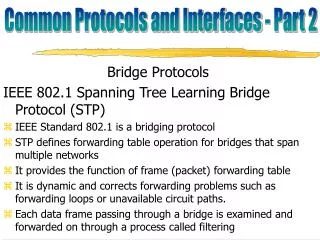
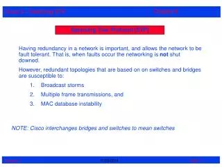
Spanning Tree Protocol (STP) • Standard: IEEE 802.1D • A loop-prevention protocol • Allows Layer 2 devices to communicate with each other to discover physical loops in the network. • STP algorithm creates a loop-free logical topology. • STP creates a tree structure of loop-free leaves and branches that spans the entire Layer 2 network. • Term "bridge": Same as "switch" • Legacy terms: Transparent and Translation bridges
Ensures that there will be only one active path to every destination. • STP executes an algorithm called Spanning Tree Algorithm (STA). • STA chooses a reference point, called a root bridge. • Then determines the available paths to that reference point. • If more than two paths exists, STA picks the best path and blocks the rest
Spanning Tree Protocol (STP) “STP often accounts for more than 50% of the configuration, troubleshooting, and maintenance headaches in real-world campus networks (especially if they are poorly designed). A complex protocol that is generally poorly understood.” Radia Perlman – Developer of STP
https://thenetworkcollective.com/2017/10/history-of-networking-radia-perlman-spanning-tree/https://thenetworkcollective.com/2017/10/history-of-networking-radia-perlman-spanning-tree/
Spanning Tree Protocol (STP)An Introduction Rick Graziani Cabrillo College graziani@cabrillo.edu
Redundancy at Layers 1, 2 and 3 Overview of Benefits and Issues Rick Graziani Cabrillo College graziani@cabrillo.edu
Redundancy: Layer 1, 2, and 3 • Redundancy is important for fail over • Layer 3 routers always forward unicasts out a single port • Single path unless there is a routing loop (misconfiguration or convergence issues) • Layer 2 switches always forward unknown unicasts out all ports • Susceptible to continuous loops, duplicate frames, MAC table instability
Ethernet without STP • Makes the LAN interoperable in seconds • Unknown unicasts • Broadcasts
Layer 2 Ethernet Frames: No TTL/Hop Limit • IP has a mechanism to prevent loops. • Unlike IP, Ethernet frames have no TTL field
Redundancy at Layers 1, 2 and 3 Overview of Benefits and Issues Rick Graziani Cabrillo College graziani@cabrillo.edu
STP DisabledDuplicate Frames and MAC Address Table Instability Rick Graziani Cabrillo College graziani@cabrillo.edu
Unknown Unicast Switch Moe learns Kahns’ MAC address. MAC Address Table Port 4: 00-90-27-76-96-93 Moe A Host Kahn A Larry Host Baran
Unknown Unicast Destination MAC is an unknown unicast, so Moe floods it out all ports. MAC Address Table Port 4: 00-90-27-76-96-93 Moe A Host Kahn A Larry Host Baran
Unknown Unicast Switch Larry records the Source MAC of the frame twice. MAC Address Table Port 4: 00-90-27-76-96-93 Moe A Host Kahn A Larry MAC Address Table Port 1: 00-90-27-76-96-93 Port A: 00-90-27-76-96-93 Host Baran
Unknown Unicast Switch Larry floods the unknown unicast out all ports, except the incoming port. MAC Address Table Port 4: 00-90-27-76-96-93 Moe A Host Kahn A Larry MAC Address Table Port A: 00-90-27-76-96-93 Host Baran
Unknown Unicast Switch Moe receives the frame, changes the MAC address table with newer information and floods the unknown unicast out all ports. MAC Address Table Port 4: 00-90-27-76-96-93 Port 1: 00-90-27-76-96-93 Moe A Host Kahn A Larry MAC Address Table Port A: 00-90-27-76-96-93 Host Baran
Unknown Unicast MAC Address Table Port 4: 00-90-27-76-96-93 Port 1: 00-90-27-76-96-93 And the cycle continues! Moe A Host Kahn A Larry MAC Address Table Port A: 00-90-27-76-96-93 Host Baran
STP DisabledDuplicate Frames and MAC Address Table Instability Rick Graziani Cabrillo College graziani@cabrillo.edu
STP Disabled: Broadcast Frames Rick Graziani Cabrillo College graziani@cabrillo.edu
STP Disabled: Broadcast Frames Rick Graziani Cabrillo College graziani@cabrillo.edu
STP – Introducing the Bridge ID and Path Cost Rick Graziani Cabrillo College graziani@cabrillo.edu
STP Prevents Loops • The purpose of STP is to avoid and eliminate loops in the network by negotiating a loop-free path through a root bridge. • STP determines where the are loops and blocks links that are redundant. • Ensures that there will be only one active path to every destination. X
Spanning Tree Algorithm X • STP executes an algorithm called Spanning Tree Algorithm (STA). • STA chooses a reference point, called a root bridge. • Then determines the available paths to that reference point. • If more than two paths exists, STA picks the best path and blocks the rest
Rick Graziani graziani@cabrillo.edu Two-key STP Concepts • STP calculations make extensive use of two key concepts in creating a loop-free topology: • Bridge ID • Path Cost
Rick Graziani graziani@cabrillo.edu Bridge ID (BID) Bridge ID Without the Extended System ID • Bridge ID (BID) is used to identify each bridge/switch. • The BID is used in determining the center of the network, in respect to STP, known as the root bridge. Bridge ID with the Extended System ID
Bridge ID (BID) • Consists of two components: • A 2-byte Bridge Priority: Cisco switch defaults to 32,768 or 0x8000. • Usually expressed in decimalformat • A 6-byte MAC address • Usually expressed in hexadecimalformat.
Bridge ID (BID) • Each switch has a unique BID. • Original 802.1D standard, the BID = Priority Field +MAC address of the switch. • All VLANs were represented by a CST – one spanning tree for all vlans (later). • PVST requires that a separate instance of spanning tree run for each VLAN • BID field is required to carry VLAN ID (VID). • Extendedsystem ID to carry a VID.
What is the BID of this switch? Core# show spanning-tree VLAN0001 Spanning tree enabled protocol ieee Root ID Priority 32769 Address 0001.964E.7EBB Cost 4 Port 25(GigabitEthernet0/1) Hello Time 2 sec Max Age 20 sec Forward Delay 15 sec Bridge ID Priority 32769 (priority 32768 sys-id-ext 1) Address 0001.C945.A573 Hello Time 2 sec Max Age 20 sec Forward Delay 15 sec Aging Time 20
Bridge ID (BID) • Used to elect a root bridge (coming) • Lowest Bridge ID is the root. • If all devices have the same priority, the bridge with the lowest MAC address becomes the root bridge. (Yikes) • Note: For simplicity, in our topologies we will use Bridge Priorities without the Extended System ID. (Same process, just done per VLAN.)
Path Cost – Original Spec (Linear) • Bridges use the concept of cost to evaluate how close they are to other bridges. • Used to create the loop-free topology . • Originally, 802.1D defined cost as 1 billion/bandwidth of the link in Mbps. • Cost of 10 Mbps link = 100 • Cost of 100 Mbps link = 10 • Cost of 1 Gbps link = 1 • Running out of room for faster switches including 10 Gbps Ethernet
Path Cost – Revised Spec (Non-Linear) • IEEE modified the most to use a non-linear scale with the new values of: • 4 Mbps 250 (cost) • 10 Mbps 100 (cost) • 16 Mbps 62 (cost) • 45 Mbps 39 (cost) • 100 Mbps 19 (cost) • 155 Mbps 14 (cost) • 622 Mbps 6 (cost) • 1 Gbps 4 (cost) • 10 Gbps 2 (cost) • You can change the path cost by modifying the cost of a port. • Exercise caution when you do this! • BID and Path Cost are used to develop a loop-free topology . • Coming very soon!
STP – Introducing the Bridge ID and Path Cost Rick Graziani Cabrillo College graziani@cabrillo.edu
STP – Introducing the STP Process (Algorithm) Rick Graziani Cabrillo College graziani@cabrillo.edu
STP Convergence and Decision Sequences STP ConvergenceStep 1 Elect one Root BridgeStep 2 Elect Root PortsStep 3 Elect Designated Ports When creating a loop-free topology, STP always uses the same five-step decision sequence: Five-Step decision Sequence Step 1:Lowest root bridge ID - Determines the root bridge Step 2:Lowest cost to the root bridge - Favors the upstream switch with the least cost to root Step 3: Lowest sender bridge ID - Serves as a tie breaker if multiple upstream switches have equal cost to root Step 4 - Lowest Port Priority - Serves as a tie breaker if a switch has multiple (non-Etherchannel) links to a single upstream switch (configurable) Step 5: Lowest sender Port ID (port priority then port ID) - Serves as a tie breaker if a switch has multiple (non-Etherchannel) links to a single upstream switch with the same priority
Key BPDU concepts BPDU key concepts: • Bridges send STP BPDUs (Bridge Protocol Data Units) on all ports every 2 seconds. • This describes their best path to the Root Bridge • As every BPDU arrives, it is checked against this five-step sequence to see if it is more attractive (lower in value) than the existing BPDU saved for that port. • Only the best value BPDU is saved.
Steps to STP Convergence STP ConvergenceStep 1 Elect one Root BridgeStep 2 Elect Root PortsStep 3 Elect Designated Ports Five-Step decision Sequence Step 1 - Lowest Root BID Step 2 - Lowest Path Cost to Root Bridge Step 3 - Lowest Sender BID Step 4 - Lowest Port Priority Step 5 - Lowest Sender Port ID • Root Port is the port closest to the Root Bridge. • Designated port is port with “best” path to root (smallest BPDU) on link • All other ports are Blocked (Undesignated Port)
Root Bridge Lowest Bridge ID is the root.
Root Ports: Best path to Root Bridge Root Port is the port closest to the Root Bridge. Designated port is port with “best” path to root (smallest BPDU) on link All other ports are Blocked (Undesignated Port)
Designated Ports – Root Bridge Root Port is the port closest to the Root Bridge. Designated port is port with “best” path to root (smallest BPDU) on link All other ports are Blocked (Undesignated Port)
Designated Ports: Which switch has best path? Root Port is the port closest to the Root Bridge. Designated port is port with “best” path to root (smallest BPDU) on link All other ports are Blocked (Undesignated Port)
Another Example BID: 24577.5555.5555.5555 BID: 24577.1111.1111.1111
STP – Introducing the STP Process (Algorithm) Rick Graziani Cabrillo College graziani@cabrillo.edu
STP Bridge Protocol Data Unit (BPDU) and Propagating BPDUs Rick Graziani Cabrillo College graziani@cabrillo.edu
There are three kinds of BPDUs: • Configuration BPDU: Provides information to all switches. • TCN (Topology Change Notification): Announces changes in the topology. • TCA (Topology Change Acknowledgment): Confirms reception of the TCN. By default the BPDUs are sent every 2 seconds.
Rick Graziani graziani@cabrillo.edu Its all done with BPDUs!
STP Bridge Protocol Data Unit (BPDU) and Propagating BPDUs Rick Graziani Cabrillo College graziani@cabrillo.edu
Danger of Disabling STP Rick Graziani Cabrillo College graziani@cabrillo.edu