Download

1 / 46
470 likes | 849 Vues
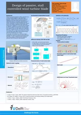
Design and Feasibility of Active Control Surfaces on Wind Turbine Blade Systems. Doug Cairns Lysle Wood Distinguished Professor Nathan Palmer, Jon Ehresman, MSME Candidates Mechanical and Industrial Engineering. Who Knows About Reliability?.

E N D
Design and Feasibility of Active Control Surfaces on Wind Turbine Blade Systems Doug Cairns Lysle Wood Distinguished Professor Nathan Palmer, Jon Ehresman, MSME Candidates Mechanical and Industrial Engineering
Who Knows About Reliability? • When an aircraft company designs and sells an airplane, its primary product is reliability. • When you get on an aircraft, you are statistically assured of its reliability. • Aircraft reliability is a SAFETY issue, wherein almost any price is acceptable; wind turbines are primarily an ECONOMIC issue. • Nonetheless, the aircraft industry has a well established track record for quantifiable reliability • The following few slides are from a Montana State University course on Aircraft Structures
How Does Boeing Do It? Delivery Boeing design requirements Validate and certify Design • Operate • Maintain In-serviceoperation Produce Regulatory requirements Continuous feedback of information
Commercial Jet Fleet Safety Record Structural Reliability is a Given; One cannot argue with the results
Structural Safety System Airworthiness authorities Regulatory Actions Fleet Surveillance Structural safety Design Fabrication Customer Support Maintenance Inspection Repair Reporting Everyone takes ownership and has a role Airline operators Airplane manufacturer
All Elements are Applicable for Probabilistic Reliability of Wind Turbines • Static Strength • Safe Life or Damage Tolerant Design • Certification Process • Manufacturing • Statistical Quality Control • Defects Quantification • Health Monitoring • Operation and Maintenance • Inspection and Repair
The Probabilistic Life Cycle for Wind Turbine Blades • Clearly, the aircraft approach is too expensive, but it has elements from which we can learn. • A notable example is the US Civil Infrastructure issue; we cannot afford to replace all structures, but we can monitor and play triage (e.g. Sandia’s blade sensor initiatives). • Some distributions are available (e.g. loads, materials) which can be convolved (Paul Veers is an expert on this topic) to begin to develop probabilistic reliability distributions.
The Key Question: Can an affordable, meaningful approach be developed for wind turbine blade reliability?
What We May Be Able to Do for Wind Turbine Blade Reliability • Form a collaboration and interaction between wind turbine manufacturers, wind turbine certifying agencies, and wind turbine operators to determine needs and hierarchy (ala Aircraft triad) • Develop lower cost methodologies for materials qualification, manufacturing details variability, and loads variability • Composite civilian aircraft structures cost approximately $500/lb; composite wind turbine blades cost $5-10/lb; rough cost for a wind turbine blade reliability program should be around 10-50 times LESS than an aircraft structures to make economic sense • Proof testing (test up to design limit load with subsequent inspections) is a proven, low cost reliability technique; eliminates early, anomalous failures (success story – filament wound rocket motor cases) • Combine materials variability, manufacturing details variability, loads variability to determine statistical reliability (easier said than done, determine if current data are useful; if not, determine what data are needed) • Determine which elements Probabilistic Life Cycle Management will yield the highest payoff to provide reliability (assessment and improvement)
Constraints for Blade Inspections • Achieving 10 – 50x lower inspection costs is a “sporty” goal • Low cost, robust sensors • Minimal labor (low cost automation) • Low cost data reduction and analysis • Inspection protocol will need to be done in the field (You cannot tow a wind turbine into a hangar for inspections) Challenge to MSU initiated circa August 2007; two year contract beginning February 2008
Enabling Technologies for In-Situ Blade Inspections • Beginning in the 1980s DARPA (Defense Advanced Research Projects Agency) invested in a broad range of low cost sensors. • Many have been commercialized • Demonstrations made on composite structures • Data Acquisition Systems have been developed which are easily programmed and implemented (e.g. LabView) Combination makes automated sensing for wind turbine blades practical
Low cost sensing, data acquisition, and data analysis are key technologies to achieve wind turbine reliability goals
Smart Wind Turbine Blades – Sensor Examples Metal Foil Strain Gauges • Created in 1938 • Uses wire resistance change to compute strain • Successful use with composites has been mixed • Most metals have <0.8% yield strain • Glass fiber composites can have ultimate strains >2% • Failure of gage may be an “early warning sign.”
Smart Wind Turbine Blades – Sensor Examples (cont.) Fiber Optic Sensing Sensing Capabilities • Strain • Displacement • Vibration • Temperature • Leak Detection • Pressure Sensor strain to failure compatible with composites
Fiber Bragg Grating • First demonstrated by Kenneth Hill in 1978 • Created by illuminating a fiber with a spatially-varying pattern of intense UV laser light • Gratings reflect a specific wavelength of light • Strains result in a change in the grating patter • Reflected wave length slightly shifted by change in pattern enabling use as sensor
Reflected Light • Each grating reflects only a small wavelength • Non-reflected waves allowed to continue on • Shift in reflected wavelength can be read http://www.bayertechnology.com/img_basis/de_Faser-Bragg-Gitter.gif http://www.sensorsmag.com/sensors/data/articlestandard/sensors/162006/321349/fig1b.gif
Smart Wind Turbine Blades – Sensor Examples (cont.) Piezoelectric Sensing • Application Ideas (specifically PVDF): • Vibration sensing (active damping) • Strain sensing • Pressure/Air flow sensing • Weather detection (rain, wind, hail intensity) • Air ranging ultrasound • Delamination non-destructive testing
Sensors Studied to Date • PVDF piezo electric sensor • Accelerometer • Metal foil strain gage • Ambient humidity sensor • Thermocouple • IR transmittance measurement • Ultrasonic transducer • Fiber optic sensors
Manufacturing Demonstrations • Embedded • Fiber optics • Foil strain gages • Thermistors • Thermocouples • PVDF piezoelectric sensors • Bonded onto blade • Foil strain gages • PVDF sensors • Fiber optics • Humidity • Accelerometers • Through transmission IR Implemented and Demonstrated in both vinyl-ester and epoxy matrix composites
Sensor Laminate Demonstrator Manufacturing and Processing Layup Infusion
Sensor Laminate Demonstrator Manufacturing and Processing (cont.) Fiber Optic Embedment SAERTEX U14EU920-00940-T1300-100000
Composite Laminate/Sensor Signal Conditioning Block Diagrams
Data Acquisition and Testing PVDF and Foil Strain Gages being Tested and Calibrated LabView Block Diagram
Preliminary Sensor Laminate Demonstrator Sample Results Foil and Piezo Strain Gages 3 Axis Accelerometer IR Emitter and Photo Transistor Humidity Sensor
Results of Embedded PVDF Piezo-electriicFilms Percent Difference between Dipped Sensors and Controls Epoxy ~ 12.6 Vinylester ~ 24.6 Percent Difference between Submerged Sensors and Controls Epoxy ~ 1.3 Vinylester ~ 21.7
Results of Embedded Fiber Optics Percent Difference between dipped Sensors and Controls Epoxy ~ 6.9 Vinylester ~ 15.5 Percent Difference between submerged Sensor and Controls Epoxy ~ 1.1 Vinylester ~ 20.3
Fiber Optic Signal During Composite Laminate Processing Mechanics of signal losses not completely understood, but observed by others
Embedded Fiber Optics(composite/fiber interface) Fiber Optic (fiber plus cladding) FEM 198x Cladding/Composite Interface FEM 757x Consistent application to composite wind turbine blades will probably require surface treatment of fiber (similar issues with all embedded sensors studied)
PVDF Film Sensors Well Bonded (200x) Poorly Bonded (50x)
Embedded Sensor Lead Wires Sensor Lead Wire FEM 1,850x Thin, polymeric insulation with questionable composite interface Sensor Lead Wire FEM 285x
Fiber Optic Embedding Development • Initially FO traveled through the layup, peel ply, and flow media unprotected • The FO did not survive the laminate extraction
Present Scheme for Fiber Optic Transition Through Layup Covering Fiber Optics with wire sheathing material This provided reliable signal input and output Small sections were cutout of the peel ply and flow media to accommodate the Fiber Optics
Progress • Low cost sensors have been implemented and demonstrated in composite wind turbine blade laminates • Sensors data acquisition has been developed in a robust, commercially-available platform • In the process of calibrating sensor outputs • Embedding sensors will not be trivial • Interface issues, preliminary results on unidirectional laminates with embedded sensors have static strength decreases • Durability and Longevity issues • Sensor • Laminate
Ongoing Work • Calibration of sensors • Manufacturing and testing of more laminates • Glass and Carbon Fiber Reinforcements • Vinyl ester, Epoxy, and DCPD Matrices • Surface treatment for composite/sensor compatibility • Mechanical • Chemical • Plasma interphases for optimization • Implementation for composite wind turbine blades • New manufacturing • Retrofit • Provide input for applications to manufacturing composite wind turbine blades with integrated sensors • Sandia/Industry Blade Development Programs • Montana Wind Applications Center (testbed for sensor research) • Continue to develop a reasonable cost approach to statistically defensible reliability
Acknowledgements This works has been done with sponsorship from Sandia National Laboratories – Wind Technology, with specific involvement from Mr. Tom Ashwill and Mr. Mark Rumsey
Montana Wind Applications Center MSU WAC GOALS Develop wind applications course-work at the University level, to address growing demand for technical employees in the wind industry. Support outreach and assistance efforts to disseminate wind energy knowledge. Support the DOE NREL Wind for Schools initiative to place wind turbines at participating K-12 Schools throughout the state of Montana. Contact: Robb Larson, P.E. Assistant Professor Dept. of Mechanical and Industrial Engineering 220 Roberts Hall Montana State University Bozeman, MT 59717 phone: 406-994-6420 fax: 406-994-6292 rlarson@me.montana.edu The new Wind Applications Center at Montana State University joins WACs at universities in 5 other western states. Additional WACs will be brought on-line each year. Funded by a National Renewable Energy Laboratory grant, the long-term goal of this nationwide program is to promote wind as a clean, viable, and sustainable energy source for today and tomorrow. PRESENT AND FUTURE WAC EFFORTS • MET “Capstone Design” Student team working on Wind Energy issues, site selection for Wind for Schools project, design/prototyping of turbine tower infrastructure • Judith Gap wind farm tour March 2008 sponsored by Invenergy LLC and Western Community Energy • Skystream 3.7 turbine installation planned for installation on MSU campus • Coordinating Outreach efforts with MSU Extension • Alternative Energy Applications course Fall 2008 • Wind Internship program under development • Additional University courses in Wind and Alternative energy applications under consideration • WAC Website going on-line May 2008