Download
1 / 27
390 likes | 928 Vues
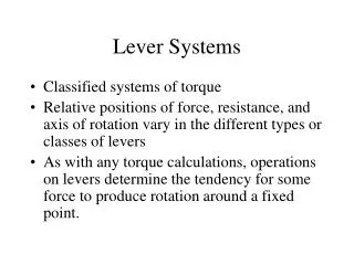
y. P. r. s. . x. O. CHAPTER 10) ROTATION OF A RIGID OBJECT ABOUT A FIXED AXIS 10.1) Angular Displacement, Velocity, and Acceleration

E N D
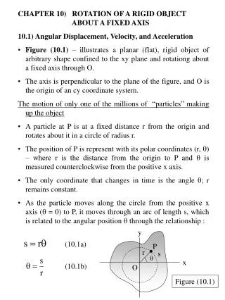
y P r s x O • CHAPTER 10) ROTATION OF A RIGID OBJECT ABOUT A FIXED AXIS • 10.1) Angular Displacement, Velocity, and Acceleration • Figure (10.1) – illustrates a planar (flat), rigid object of arbitrary shape confined to the xy plane and rotationg about a fixed axis through O. • The axis is perpendicular to the plane of the figure, and O is the origin of an cy coordinate system. • The motion of only one of the millions of “particles” making up the object • A particle at P is at a fixed distance r from the origin and rotates about it in a circle of radius r. • The position of P is represent with its polar coordinates (r, ) – where r is the distance from the origin to P and is measured counterclockwise from the positive x axis. • The only coordinate that changes in time is the angle ; r remains constant. • As the particle moves along the circle from the positive x axis ( = 0) to P, it moves through an arc of length s, which is related to the angular position through the relationship : (10.1a) (10.1b) Figure (10.1)
y Q, tf r P, ti f i x O • Units of in Equation (10.1b) • is the ratio of an arc length and the radius of the circle – it is a pure number. • We commonly give the artificial unit radian (rad), where : one radian is the angle subtended by an arc length equal to the radius of the arc. • Because the circumference of a circle is 2r – from Equation (10.1b), 360o corresponds to an angle of (2r /r) rad = 2 rad (one revolution). • Hence, 1 rad = 360o / 2 57.3o • To convert an angle in degrees to an angle in radians – use the fact that 2 rad = 360o : • For example, 60o equal /3 rad, and 45o equals /4 rad. • The particle in question on our rigid object travels from position P to position Q in a time t - Figure (10.2) • The radius vector sweeps out an anlge = f - i . Figure (10.2)
This quantity is defined as the angular displacement of the particle : • The average angular speed (omega) = the ratio of this angular displacement to the time interval t : • The instantaneous angular speed is defined as the limit of the ratio / t as t approaches zero : • Angular speed has units of radians per second (rad / s), or second-1 (s-1) – because radians are not dimensional. • is positive when is increasing (counterclockwise motion). • is negative when is decreasing (clockwise motion). • If the instantaneous angular speed of an object changes from i to f in the time interval t - the object has an angular acceleration. • The average angular acceleration (alpha) of a rotating object is defined as the ratio of the change in the angular speed to the time interval t : (10.2) (10.3) (10.4) t0
(10.5) (10.6) t0 Average angular acceleration • The instantaneous angular acceleration is defined as the limit of the ratio / t as t approaches zero : • Angular acceleration has units of radians per second squared (rad / s2), or just second-2 (s-2). • is positive when the rate of counterclockwise rotation is increasing or when the rate of clockwise rotation is decreasing. • When rotating about a fixed axis, every particle on a rigid object rotates through the same angle and has the same angular speed and the same angular acceleration. • That is, the quantities , , and characterize the rotational motion of the entire rigid object. • Angular position (), angular speed (), and angular acceleration () are analogous to linear position (x), linear speed (v), and linear acceleration (a). • The variable , , and differ dimensionally from the variables, x, v, and a only by a factor having the unit of length.
Direction of and • These variables are the magnitudes of the angular velocity and the angular acceleration vectors and , respectively – they should always be positive. • Because considering rotation about a fixed axis – indicate the directions of the vectors by assigning a positive or negative sign to and • For rotation about a fixed axis, the only direction that uniquely specifies the rotational motion is the direction along the axis of rotation. • Therefore, the direction of and are along this axis. • If an object rotates in the xy plane as in Figure (10.1) – the direction of is out of the plane of the diagram when the rotation is counterclockwise and into the plane of the diagram when the rotation is clockwise. • Right-hand rule (Figure (10.3)) – when four fingers of the right hand are wrapped in the direction of rotation, the extended right thumb points in the direction of . • The direction of follows from its definition d / dt. • It is the same as the direction of if the angular speed is increasing in time, and it is antiparallel to if the angular speed is decreasing in time.
(for constant ) (10.7) (for constant ) (10.8) Rotational kinematic equations (for constant ) (10.9) • 10.2) Rotational Kinematics : Rotational Motion with Constant Angular Acceleration • For rotational motion about a fixed axis, the simplest accelerated motion to analyze is motion under constant angular acceleration. • Develop kinematic relationships for this type of motion. • Equation (10.6) in the form d = dt, and let ti = 0 and tf = t, we can integrate this expression directly : • Substituting Equation (10.7) into Equation (10.4) and integrating once more we obtain : • If we eliminate t from Equations (10.7) and (10.8), we obtain : • The same form as those for linear motion under constant linear acceleration with the substitutions x , v , and a . • Table (10.1) compares the kinematic equations for rotational and linear motion.
Table (10.1) : Kinematic Equation for Rotational and Linear Motion Under Constant Acceleration Example (10.1) : Rotating Wheel A wheel rotates with a constant angular acceleration of 3.50 rad/s2. If the angular speed of the wheel is 2.00 rad/s at ti = 0, (a) through what angle does the wheel rotate in 2.00 s? (b) What is the angular speed at t = 2.00 s?
10.3) Angular and Linear Quantities • Derive some useful relationships between the angular sped and acceleration of a rotating rigid object and the linar speed and acceleration of an arbitrary point in the object. • When a rigid object rotates about a fixed axis (Figure (10.4)) – every particle of the object moves in a circle whose center is the axis of rotation. • Relate the angular speed of the rotating object to the tangential speed of a point P on the object. • Because point P moves in a circle, the linear velocity vector v is always tangent to the circular path = tangential velocity. • The magnitude of the tangential velocity of the point P is by definition the tangential speed v = ds / dt, where s is the distance traveled by this point measured along the circular path. • Recalling that s = r (Eq. (10.1a)) and noting that r is constant, we obtain : • Because d / dt = (Eq. (10.4)) : (10.10) The tangential speed of a point on a rotating rigid object = the perpendicular distance of that point from the axis of rotaion multiplied by the angular speed
Relationship between linear and angular acceleration (10.11) • Although every point on the rigid object has the same angular speed, not every point has the same linear speed because r is not the same for all points on the object. • Equation (10.10) – the linear speed of a point on the rotating object increases as one moves outward from the center of rotation. • Relate the angular acceleration of the rotating rigid object to the tangential acceleration of the point P by taking the time derivative of v : The tangential component of the linear acceleration of a point on a rotationg rigid object = the point’s distance from the axis of rotation multiplied by the angular acceleration.
A point rotating in a circular path undergoes a centripetal, or radial, acceleration ar of magnitude v2 / r directed toward the center of rotaion – Figure (10.5). • Because v = r for a point P on a rotating object, the radial acceleration of that point can be expressed as : • The total linear acceleration vector of the point is a = at + ar . • at - describes the change in how fast the point is moving. • ar - represents the change in its direction of travel. • Because a is a vector having a radial and a tangential component, the magnitude of a for the point P on the rotating rigid object is : (10.12) (10.13)
y vi mi ri x O • 10.4) Rotational Energy • Kinetik energy of a rotating rigid object • Consider the object as a collection of particles and assume that it rotates about a fixed z axis with an angular speed (Figure (10.7)). • Each particle has kinetic energy determined by its mass and linear speed. • If the mass of the ith particle is mi and its linear speed is vi, its kinetic energy is : • Every particle in the rigid object has the same angular speed . • The individual linear speeds depend on the distance ri from the axis of rotation according to the expression vi = ri (Figure (10.7)
(10.15) Rotational kinetic energy (10.16) • The total kinetic energy of the rotating rigid object is the sum of the kinetic energies of the individual particles : • We can write this expression in the form : • where we have factored 2 from the sum because it is common to every particle. • The quantity in parentheses (Equatioan (10.14)) is the moment of inertia I : • From the definition of moment of inertia – it has dimensions of ML2 (kg·m2 in SI units). • Equation (10.14) becomes : • The moment of inertia = a measure of the resistance of an object to changes in its rotational motion (just as mass is a measure of the tendency of an object to resist changes in its linear motion). • I depends on the physical arrangement of that mass. (10.14)
y m b M a a M x O b m Example (10.3) : The Oxygen Molecule Consider an oxygen molecule (O2) rotating in the xy plane about the z axis. The axis passes through the center of the molecule, perpendicular to its length. The mass of each oxygen atom is 2.66 x 10⁻²⁶ kg, and at room temperature the average separation between the two atoms is d = 1.21 x 10⁻¹⁰ m (the atoms are treated as point masses). (a) Calculate the moment of inertia of the molecule about the z axis. (b) If the angular speed of the molecule about the z axis is 4.60 x 10¹² rad/s, what is its rotational kinetic energy? Example (10.4) : Four Rotating Masses Four tiny spheres are fastened to the corners of a frame of negligivle mass ying in the xy plane (Fig. 10.8). We shall assume that the spheres’ radii are small compared with the dimensions of the frame. (a) If the system rotates about the y axis with an angular speed , find the moment of inertia and the rotational kinetic energy about this axis. (b) Suppose the system rotates in the xy plane aout an axis through O (the z axis). Calculate the moment of inertia and rotational kinetic energy about this axis. Figure (10.8)
10.5) Calculation of Moments of Inertia • Evaluate the moment of inertia of an extended rigid object by imagining the object divided into many small volume elements, each of which has mass m. • Use the definition I = ri2 mi and take the limit of this sum as m 0. • In this limit, the sum becomes an integral over the whole object : • It is usually easier to calculate moments of inertia in terms of the volume of the elements rather that their mass. • Make that change by using Equation (1.1), = m / V, where is the density of the object and V is its volume. • In its differential form = dm / dV (because the volumes are very small). • Solving for dm = dV and substituting the result into Equation (10.17) gives : • If the object is homogeneous, then is constant and the integral can be evaluated. • If is not constant, then its variation with position must be known to complete the integration. i mi 0 (10.17)
Ways of expressing density • When relates to volume V : volume density = m / V which is the mass per unit volume. • When dealing with a sheet of uniform thickness t : surface density = t , which signifies mass per unit area. • When mass is distributed along a uniform rod of cross-sectional area A : linear density = M / L = A, which is the mass per unit length. • Example (10.5) : Uniform Hoop • Find the moment of inertia of a uniform hoop of mass M and radius R about an axis perpendicular to the plane of the joop and passing through its center (Figure (10.9)). y dm Figure (10.9) x O R
y’ y dx x O x L Example (10.6) : Uniform Rigid Rod Calculate the moment of inertia of a uniform rigid rod of length L and mass M (Figure (10.10)) about an axis perpendicular to the rod (the y axis) and passing through its center of mass. Figure (10.10)
z r dr R L Example (10.7) : Uniform Solid Cylinder A uniform solid cylinder has a radius R, mass M, and length L. Calculate its moment of inertia about its central axis (the z axis in Figure (10.11)). Figure (10.11)
(10.18) • Table (10.2) gives the moments of inertia for a number of bodies about specific axes. • Parallel-axis theorem • Suppose the moment of inertia about an axis through the center of mass of an object is ICM. • The parallel-axis theorem states that the moment of inertia about any axis parallel to and a distance D away from this axis is :
Example (10.8) : Applying the Parallel-Axis Theorem Consider once again the uniform rigid rod of mass M and lenth L shown in Figure (10.10). Find the moment of inertia of the rod about an axis perpendicular to the rod through one end (the y’ axis in Figure (10.10)).
Definition of torque (10.19) • 10.6) Torque • When a force is exerted on a rigid object pivoted about an axis, the object tends to rotate about that axis. • The tendency of a force to rotate an object about some axis is measured by a vector quantity = torque (tau). • Consider the wrench pivoted on the axis through O in Figure (10.13). • The applied force F acts at an angle to the horizontal. • The magnitude of the torque associated with the force F : • where r = the distance between the pivot point and the point of application of F, d = the perpendicular distance from the pivot point to the line of action of F. • From the right triangel in Figure (10.13) – the wrench is its hypotenuse : d = r sin • d = moment arm (or lever arm) of F. • Torque is defined only when a reference axis is specified. • Torque is the product of a force and the moment arm of that force. • Moment arm is defined only in terms of an axis of rotation.
Figure (10.13) – the only component of F that tends to cause rotation is F sin (the component perpendicular to r. • The horizontal component F cos - has no tendency to produce rotation because it passes through O. • From the definition of torque – the rotating tendency increases as F increases and as d increases. • If two or more forces are acting on a rigid object • Each forces tends to produce rotation about the pivot at O. • Figure (10.14) – F2 tends to rotate the object clockwise, and F1 tends to rotate it counterclockwise. • The sign of the torque resulting from a force is positive if the turning tendency of the force is counterclockwise and is negative if the turnig tendency is clockwise. • Figure (10.14) – the torque resulting from F1, which has a moment arm d1, is positive and equal to + F1d1. • Figure (10.14) – the torque from F2 is negative and equal to – F2d2. • The net torque about O is :
Torque should not be confused with force and work • Force can cause a change in linear motion, as described by Newton’s second law. • Forces can also cause a change in rotational motion, but the effectiveness of the forces in causing this change depends on both the forces and the moment arms of the forces, in the combination that we call torque. • Torque has units of force times length - newton·meters in SI units (same units as work, but are very different consepts). • Example (10.9) : The Net Torque on a Cylinder • A one-piece cylinder is shaped as shown in Figure (10.15), with a core section protruding from the larger drum. The cylinder is free to rotate around the central axis shown in the drawing. A rope wrapped around the drum, which has radius R1, exerts a force F1 to the right on the cylinder. A rope wrapped around the core, which has radius R2, exerts a force F2 downward on the cylinder. (a) What is the net torque acting on the cylinder about the rotation axis (which is the z axis in Figure (10.15))?
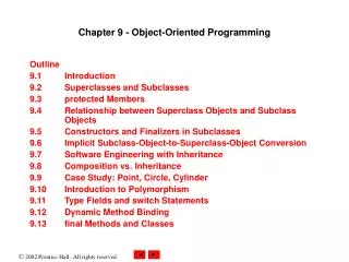
F ds d P O r • 10.8) Work, Power, and Energy in Rotational Motion • Consider the relationship between the torque acting on a rigid object and its resulting rotational motion in order to generate expressions for the power and a rotational analog to the work-kinetic energy theorem. • Figure (10.22) – the rigid object pivoted at O. • Suppose a single external force F is applied at P, where F lies in the plane of the page. • The work done by F as the object rotates through an infinitesimal distance ds = r d in a time dt is : • where F sin is the tangential component of F (the component of the force along the displacement). • The radial component of F does no work because it is perpendicular to the displacement. Figure (10.22)
Because the magnitude of the torque due to F about O is defined as rF sin (Equation (10.19)) – the work done for the infinitesimal rotation is : • The rate at which work is being done by F as the object rotates about the fixed axis is : • Because dW/dt is the instantaneous power P delivered by the force, and because d/dt = , this expression reduces to : • This expression is analogous to P = Fv in the case of linear motion, and the expression dW = d is analogous to dW = Fx dx. • Work and Energy in Rotational Motion • When a symmetric object rotates about a fixed axis – the work done by external forces equals the change in the rotational energy. (10.22) Power delivered to a rigid object (10.23)
To show that this is in fact the case • From = I , using the chain rule from the calculus, we can express the resultant torque as : • Rearranging this expression and noting that d = dW, we obtain : • Integrating this expression, we get for the total work done by the net external force acting on a rotating system : • where the angular speed changes form I to f as the angular position changes from I to f. • That is : (10.24) Work-kinetic energy theorem for rotational motion The net work done by external forces in rotating a symmetric rigid object about a fixed axis equals the change in the object’s rotational energy.
O Ei = U = MgL/2 L/2 O’ Ef = KR = ½ I2 Example (10.14) : Rotating Rod Revisited A uniform rod of length L and mass M is free to rotate on a frictionless pin passing through one end (Figure (10.23)). The rod is released from rest in the horizontal position. (a) What is its angular speed when it reaches its lowest position? (b) Determine the linear spedd of the center of mass and the linear speed of the lowest point on the rod when it is in the vertical position. Figure (10.23)
R m2 h h m1 Example (10.15) : Connected Cylinders Consider two cylinders having masses m1 and m2 , where m1 m2 , connected by a string passing over a pulley, as shown in Figure (10.24). The pulley has a radius R and moment of inertia I about its axis of rotation. The string does not slip on the pulley, and the system is released from rest. Find the linear speeds of the cylinders after cylinder 2 descends through a distance h, and the angular speed of the pulley at this time. Figure (10.24)