Measurement of kinematic quantities through simple experiments
580 likes | 782 Vues
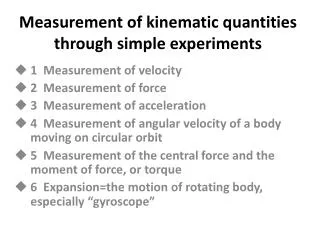
Measurement of kinematic quantities through simple experiments . 1 Measurement of velocity 2 Measurement of force 3 Measurement of acceleration 4 Measurement of angular velocity of a body moving on circular orbit

Measurement of kinematic quantities through simple experiments
E N D
Presentation Transcript
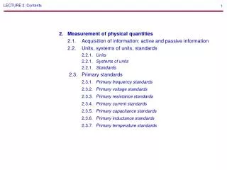
Measurement of kinematic quantities through simple experiments 1 Measurement of velocity 2 Measurement of force 3 Measurement of acceleration 4 Measurement of angular velocity of a body moving on circular orbit 5 Measurement of the central force and the moment of force, or torque 6 Expansion=the motion of rotating body, especially “gyroscope”
1 Measurement of velocity (1) Using a stop watch and a measure Exercise1L=10m, required time t=0.50s, ask the velocity of the vehicle. V=( 10 )/( 0.50 )=( 20 )m/s a body moving distance L [m], time taken t [s], the velocity v [m/s] ①
(2) Using a points recording timer (ⅰ)measuring time very short as possible t : large ⇒ v : average t : small ⇒ v : instant (ⅱ) marking points on a body periodically at very short time Fig.1 marking points Fig.2 points recording timer
Fig.3 principle of points recording timer iron bar carbon iron core paper spring coil paper tape AC Using 50Hz ⇒(ⅰ) number of vibration of the iron bar per second is 50. AC supply ⇒(ⅱ) periodic pointing number per second is 50. ⇒(ⅲ) the time between adjacent points becomes (1 / 50) [s].
Now, the time duration between points can be set (1 / 50), or (1 / 10) seconds . Exercise 2 period time is (1/10)seconds. paper tape Nr.Point0 1 2 3 4 5 Length cm 0 2.5 5.0 7.5 1 0.0 12.5 Asking for the velocity of the body. 0-1 v={(2.5−0.0)/100}/(1/10)= 0.25m/s 1-2 v={(5.0−2.5)/100}/(1/10)= 0.25m/s 2-3 v= Caution for this equipment. (ⅰ) To set the side of the paper tape chemicals painted upwards. (ⅱ) Discharge electrode may be corrupted by putting a tape from the other side. (ⅲ) Turn on the power switch after all have been set.
Now, the time duration between points can be set (1 / 50), or (1 / 10) seconds . Exercise 2 period time is (1/10)seconds. paper tape Nr.Point0 1 2 3 4 5 Length cm 0 2.5 5.0 7.5 1 0.0 12.5 Asking for the velocity of the body. 0-1 v={(2.5−0.0)/100}/(1/10)= 0.25m/s 1-2 v={(5.0−2.5)/100}/(1/10)= 0.25m/s 2-3 v= {(7.5–5.0)/100}/(1/10)=0.25m/s Caution for this equipment. (ⅰ) To set the side of the paper tape chemicals painted upwards. (ⅱ) Discharge electrode may be corrupted by putting a tape from the other side. (ⅲ) Turn on the power switch after all have been set.
Experiment 1 To measure the velocity of linear motion of the hand . Installationpoints recording timer, paper tape, ruler measure Procedure points timer (1/10)sec a hand after setting, switching ON, and pulling the tape
Experiment 1 To measure the velocity of linear motion of the hand. Installationpoints recording timer, paper tape, ruler measure Procedure points timer (1/10)sec a hand after setting, switching ON, and pulling the tape
Experiment 2 Motion of hovering soccer ball. rotating fan Points on paper tape air layer lined up almost evenly. ⇓ constant velocity linear motion or, uniform motion. Points recording timer ball paper tape
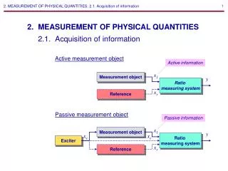
Fig.4 principle sw1 sw2 two light switches (3) Using “Be-Spe” Fig.5 Be-Spe (ⅰ) When the body has interrupted one⇒the timer switch is ON (ⅱ) next it interrupts the other one ⇒ the timer switch is OFF (ⅲ) Internal computer calculates and shows the value of the velocity.
Experiment 3To measure the velocity of small steel balls moving inside the tube. Installation“Be-Spe”, transparency tube, small steel ball Be-Spe height
Experiment 3To measure the velocity of small steel balls moving inside the tube. Installation“Be-Spe”, transparency tube, small steel ball Be-Spe height
2 Measurement of force Fig.6 (1)dynamics trucks Dynamicstruck wears a four wheels whose axle is held in ball bearings, so wheel rotation is very smooth. Rolling friction is 1 / 10 or less Dynamic friction. close to the constant motion
Experiment4To depart two trucks. Making two trucks confront each other. Releasing the coil spring ⇒ Two trucks detach with the same speed. Correctly speaking, detach with same acceleration. Naturally, it causes in the case mass of trucks are equal. (2)The third law of motion = law of action and reactionFig.7 action, reaction A B Force is that a body operates to other body. a body A operates a force to a body B, ⇔ the body B operates a force to the body A.
Fig.9 M g 0.98N 100gw F=Mg 100g Fig.8 Drawing together Each force equals (3) To measure forces by a spring balance In many cases we use a scale or a spring balance. Especially a spring balance is often used. For example they are used when checking action reaction law. gravity force for the body of 100 g ⇒ 0.98 [N] ⇒ roughly equals 1 [N]
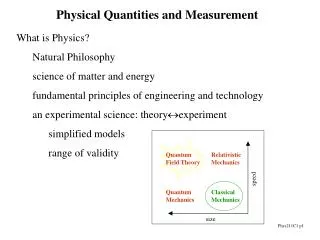
3 Measurement of acceleration (1) Acceleration Acceleration is said the variation of the velocity vector divided by the time at a extremely short time.②
(2)Constant acceleration motion If the velocity of a body becomes to v1 from v0 in a very short time Δt, the acceleration is ③ If you can measure xi, body position, at extremely short cycle time Δt each, you can calculate the velocity. For example, if you can measure x0, x1, x2 , Next, assuming this velocity varies between the time Δt, then the acceleration a in the time is got.
Experiment6To do the same construction as Exp.1, and pull the paper tape at a accelerated velocity. Provided that period time is (1/10) s.
Experiment6To do the same construction as Exp.1, and pull the paper tape at a accelerated velocity. Provided that period time is (1/10) s.
(3)To check out the relation between force and acceleration=the second law The acceleration is proportional to the force and inversely proportional to mass. Experiment7-1pulling twice of power? and also, make truck mass be twice? installationdynamics truck(0.50kg), spring balance, plane board, weight(0.25kg✕2), points timer (period time is 1/10 s) spring balance truck points timer Continue pulling the truck by ways of 3 type following. (ⅰ)Pull the truck by the balance with the dial at 0.50[N]. (ⅱ) Pull the truck by the balance with the dial at 1.0[N]. (ⅲ)Put 2 weights upon the truck, and pull with the dial at 1.0[N].
Though you pull the trucks by the balance with the dial constantly, of course, as the trucks will be accelerated, you should make the balance move the same movement as the trucks. From the paper tape to calculate velocity and acceleration.
Though you pull the trucks by the balance with the dial constantly, of course, as the trucks will be accelerated, you should make the balance move the same movement as the trucks. From the paper tape to calculate velocity and acceleration.
Experiment7-2By gravity imposed on weight, to pull trucks. It is hard pulling with constant force. making gravitational force of weight pull a truck. But approximately and provisionally proportional. Installation points timer(period time 1/10 s), 50g-weight, pulley, plane board, strap(fishing line), timer pulley truck weight
Then make the weight pull the truck in the three types below. (ⅰ)Pull with 50g-weight (ⅱ) Pull with 50g-weight✕2 (ⅲ)Pull a truck and 2 weights on it with 50g-weight✕2 From the paper tape to calculate velocity and acceleration.
Then make the weight pull the truck in the three types below. (ⅰ)Pull with 50g-weight (ⅱ) Pull with 50g-weight✕2 (ⅲ)Pull a truck and 2 weights on it with 50g-weight✕2 From the paper tape to calculate velocity and acceleration.
Experiment8(demonstration) To make a weight attached a paper tape free fall, and to measure the distances of points. timer (ⅰ) Set a paper tape through a points timer (period time 1/10 s). (ⅱ) Attach the paper tape end to a weight. (ⅲ) Fall the weight free. (ⅳ) Calculation. weight (4) To determine the value of the gravitational acceleration The value can be obtained by doing the following way. Though we can ask the value by easier method in the Exp.9.
(5)To determine the gravitational acceleration by fall distance and velocity If you free fall at the field of gravitational acceleration g, as a = g, v0 = 0 v2= 2 g xexists, Therefore g = v2 / 2 x⑤ Namely, at a point x [m] fallen if you measure the velocity v [m / s], g can be obtained by a calculation.
small ball x tube Be-Spe v Experiment 9Using Be-Spe To measure the velocity of a steel ball at the point where the ball have fallen a certain distance. Installation Be-Spe, transparency tube, small ball distance x reached velocity v ⇒ g = v2 / 2 x
small ball x tube Be-Spe v Experiment 9Using Be-Spe To measure the velocity of a steel ball at the point where the ball have fallen a certain distance. Installation Be-Spe, transparency tube, small ball distance x reached velocity v ⇒ g = v2 / 2 x
Fig.10 radius r Θ 60°π/3, 360°( ) 45° ( ), 180°( ) 30° ( ), 90° ( ) 4Measurement of angular velocity of a body moving on circular orbit (1)The rotational or revolutionary motion a round a certain center. central angle ⇒ angle of gyration The unit is“radian”[rad]. Here, if we put θ[rad] for Θ[degree] 2π✕Θ / 360 =θ⑥ the arc length l for central angle θ[rad] is following l = rθ ⑦ (2)Angular velocity in very short time Δt the angle of gyration Δθ the angular velocity refers to below.
Fig.10 radius r Θ • 60° /3, 360°( 2 ) • 45° ( /4 ), 180°( ) • 30°( /6), 90°( /2) 4Measurement of angular velocity of a body moving on circular orbit (1)The rotational or revolutionary motion a round a certain center. central angle ⇒ angle of gyration The unit is“radian”[rad]. Here, if we put θ[rad] for Θ[degree] 2π✕Θ / 360 =θ⑥ the arc length l for central angle θ[rad] is following l = rθ ⑦ (2)Angular velocity in very short time Δt the angle of gyration Δθ the angular velocity refers to below.
Fig.11 during Δt Δθ ⑧ (3)Uniform circular motion the motion with constant angular velocity ω ⇓ uniform circular motion ⇓ the tangential velocity v Mv Fig.12 tangential velocity r v ω angular velocity ω v = rω ⑨ The number of rotation per second n [c/s], or the number of per • minute N [rpm], or one rotation period time T [s], there are relationships such as n = 1 / T, ω = 2πn= 2π/T, As well, n = N/60 ⑩
Experiment10To measure the velocity of the small balls moving on circular orbit with inertia, and to calculate the angular velocity. Installation Be-Spe2pieces, transparency tube, small ball of steel or glass r=0.50, the tube edge to 10 cm height. ω= v/r =(average velocity)/0.50= 2.0✕(average velocity)
Experiment10To measure the velocity of the small balls moving on circular orbit with inertia, and to calculate the angular velocity. Installation Be-Spe2pieces, transparency tube, small ball of steel or glass r=0.50, the tube edge to 10 cm height. ω= v/r =(average velocity)/0.50= 2.0✕(average velocity)
experiment 11 (calculation) To calculate the angular velocity of the rotating top. installationtop, stop watch, movie camera, movie application and PC procedure Taking photograph of the spinning top with the stopwatch,andmake it slow-motion replay, and measure the time and angle of rotation, Then, calculate the angular velocity. Δt = 2m 01s 49 - 2m 01s 39= 0.10 s, θ =2π Angular velocity of rotating top ω is ω= 2π/0.10 =()[rad/s] Number of revolution per second n is n = 1 / T =1 / 0.10 =()[s-1]
experiment 11 (calculation) To calculate the angular velocity of the rotating top. installationtop, stop watch, movie camera, movie application and PC procedure Taking photograph of the spinning top with the stopwatch,andmake it slow-motion replay, and measure the time and angle of rotation, Then, calculate the angular velocity. Δt = 2m 01s 49 - 2m 01s 39= 0.10 s, θ =2π Angular velocity of rotating top ω is ω= 2π/0.10 =(62.8)[rad/s] Number of revolution per second n is n = 1 / T =1 / 0.10 =( 10 )[s-1]
Experiment12To messure the angular velocity of the rotating top another way. Installation top, points recording timer, paper tape, Be-spe, transparency tape (ⅰ) Rotating the top attached with a tape. (ⅱ) Rotating the top with a transparency tape. points timer
∆v ωΔt r r ωΔt With the variation of velocity during time Δt, only direction is changed, and the change is oriented to center. Δv=v✕ωΔt 5 Measurement of the central force and the moment of force, or torque Fig.13 (1)Central force Of the body, which doing free movement without force in space, the motion of the center of gravity and the motion of rotation around a fixed point are saved. Simply put, those remain constant. The value of the acceleration = rω2⑪ The magnitude of central force of the body m doing uniform circular motion f = mrω2⑫
strap(length 30 cm) 10g cylinder 2 rev. per 1sec. balance Experiment 13To ask for a central force. Installation slimcylinder like a Ball-pointpen barrel (polyvinyl chloride) Rotating the weight (period time 0.50 seconds) ⇓ Measuring the scale value. Note that because a weight rotating at high speed it can be dangerous.
strap(length 30 cm) 10g cylinder a weight 50g Note that because a weight rotating at high speed it can be dangerous. Then instead of pulling by a balance, you set down 50 g weight. How you make the rotation for weight be still in the air? ( )
strap(length 30 cm) 10g cylinder a weight 50g Note that because a weight rotating at high speed it can be dangerous. Then instead of pulling by a balance, you set down 50 g weight. How you make the rotation for weight be still in the air? ( approx. 2rev. per 1 sec. )
Fig.14 M ω Mrω2 (2)Think of centrifugal force ⇓ m Receiving a central force, Grasping a centrifugal force. mrω2 The sizes are equal. The directions are inverse. (centrfugal force) =(magnification)✕(gravity force at ground level) m r ω2 = x×m g, therefore x =r ω2 / g⑬ Then, by this value, you can express the centrifugal force is x times g.
10m Exercise 3To get a gravity by rotation as large as the Earth surface gravity. The spinning donut-shaped space ship of 20 m in diameter is rotating. Gravity is similar with on Earth. the rotating period? The case is rω2 = g ω2 = 9.8 / 10 = 0.98 ω = T = 2π / ω = 2 × 3.14 / =( )[s]
10m Exercise 3To get a gravity by rotation as large as the Earth surface gravity. The spinning donut-shaped space ship of 20 m in diameter is rotating. Gravity is similar with on Earth. the rotating period? The case is rω2 = g ω2 = 9.8 / 10 = 0.98 ω = T = 2π / ω = 2 × 3.14 / =( 6.3 )[s]
ω (3)A centrifugal separator Fig.15 centrifugal separation If you impose the large gravitational force by rotating a body.depending on slight difference in density you can layer in fluid each powder or fluid.
ω (3)A centrifugal separator Fig.15 centrifugal separation If you impose the large gravitational force by rotating a body.depending on slight difference in density you can layer in fluid each powder or fluid.
Fig.17 a force accelerates C.G. and rotates whole body around C.G. force F, Δt sec Fig.16 (-) f r (+) axis of rotation (4)Measurement of the moment of force=for the body with certain volume If the direction of the resultant force F is out of the center of gravity, force acts as rotating the body. a physical quantity of starting rotation ⇒ a moment of force “N”. In many cases, this is calculated around the center of gravity or the fulcrum. N = f1 r1 + f2 r2 +f3 r3 +⑭(units are [Nm] (Newtonmeter))
direction f fig.18 of N angular velocity Exercise5To sum up moments of force. (ⅰ) 0.5m CG 0.5m Result force is obtainable by adding vectorially. To put downward on fig. positive. 0.5N1.0N(ⅰ)0.5 + 1.0 = 1.5 N (ⅱ)1.0 + (-2.0) = ( )N (ⅱ)2.0N 0.5m CG 0.5m The moment of force around the point G is obtained. To put counterclockwise on fig. positive. • 1.0N (ⅰ)0.5✕0.5 – 1.0✕0.5 = -0.25 Nm (ⅱ)1.0✕0.5 + 2.0✕0.0 =( )Nm Moment of force makes vector. the direction of moment of force the direction of angular velocity ⇓ “right screw direction”⇒ all turning or revolving motion
direction f fig.18 of N angular velocity Exercise5To sum up moments of force. (ⅰ) 0.5m CG 0.5m Result force is obtainable by adding vectorially. To put downward on fig. positive. 0.5N1.0N(ⅰ)0.5 + 1.0 = 1.5 N (ⅱ)1.0 + (-2.0) = ( −1.0)N (ⅱ)2.0N 0.5m CG 0.5m The moment of force around the point G is obtained. To put counterclockwise on fig. positive. • 1.0N (ⅰ)0.5✕0.5 – 1.0✕0.5 = -0.25 Nm (ⅱ)1.0✕0.5 + 2.0✕0.0 =( 0.5)Nm Moment of force makes vector. the direction of moment of force the direction of angular velocity ⇓ “right screw direction”⇒ all turning or revolving motion
Experiment14Acting two forces for a body in the certain size, and making balance by third force. Pulling two balances ⇓ The ruler moving ⇓ Clips For the ruler being still ⇓ By the third balance Pulling where? (ⅰ) magnitude=( )N, position=length from left end=()m (ⅱ) magnitude=()N, position=length from left end=()m Making a ruler be body, pulling by spring balances, we look actual example. (ⅰ) 50cm 50cm 0.5N 1N (ⅱ) 2N 1N (the value indicated by the third balance)=(the deductive sum of two forces) (around every position the sum of the moment of force) = 0