Download
1 / 31
330 likes | 526 Vues
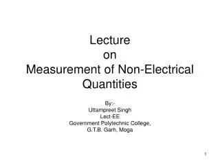
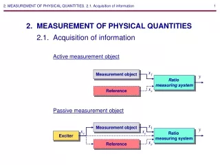
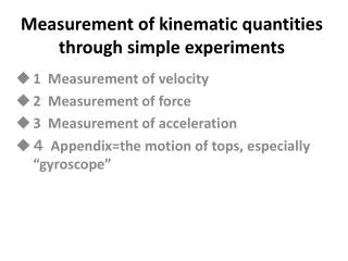
Measurement of kinematic quantities through simple experiments. 1 Measurement of velocity 2 Measurement of force 3 Measurement of acceleration 4 Appendix=the motion of tops, especially “gyroscope”. 1 Measurement of velocity. (1) Using a stop watch and a measure.

E N D
Measurement of kinematic quantities through simple experiments 1 Measurement of velocity 2 Measurement of force 3 Measurement of acceleration 4 Appendix=the motion of tops, especially “gyroscope”
1 Measurement of velocity (1) Using a stop watch and a measure Exercise1L=10m, required time t=0.50s, ask the velocity of the vehicle. V=( 10 )/( 0.50 )=( 20 )m/s a body moving distance L [m], time taken t [s], the velocity v [m/s] ①
(2) Using a points recording timer (ⅰ)measuring time very short as possible t : large ⇒ v : average t : small ⇒ v : instant (ⅱ) marking points on a body periodically at very short time Fig.1 marking points Fig.2 points recording timer
Fig.3 principle of points recording timer iron bar carbon iron core paper spring coil paper tape AC Using 50Hz ⇒(ⅰ) number of vibration of the iron bar per second is 50. AC supply ⇒(ⅱ) periodic pointing number per second is 50. ⇒(ⅲ) the time between adjacent points becomes (1 / 50) [s].
Now, the time duration between points can be set (1 / 50), or (1 / 10) seconds . Exercise 2 period time is (1/10)seconds. paper tape Nr.Point0 1 2 3 4 5 Length cm 0 2.5 5.0 7.5 1 0.0 12.5 Asking for the velocity of the body. 0-1 v={(2.5−0.0)/100}/(1/10)= 0.25m/s 1-2 v={(5.0−2.5)/100}/(1/10)= 0.25m/s 2-3 v= Caution for this equipment. (ⅰ) To set the side of the paper tape chemicals painted upwards. (ⅱ) Discharge electrode may be corrupted by putting a tape from the other side. (ⅲ) Turn on the power switch after all have been set.
Now, the time duration between points can be set (1 / 50), or (1 / 10) seconds . Exercise 2 period time is (1/10)seconds. paper tape Nr.Point0 1 2 3 4 5 Length cm 0 2.5 5.0 7.5 1 0.0 12.5 Asking for the velocity of the body. 0-1 v={(2.5−0.0)/100}/(1/10)= 0.25m/s 1-2 v={(5.0−2.5)/100}/(1/10)= 0.25m/s 2-3 v= {(7.5–5.0)/100}/(1/10)=0.25m/s Caution for this equipment. (ⅰ) To set the side of the paper tape chemicals painted upwards. (ⅱ) Discharge electrode may be corrupted by putting a tape from the other side. (ⅲ) Turn on the power switch after all have been set.
Experiment 1 To measure the velocity of linear motion of the hand . Installationpoints recording timer, paper tape, ruler measure Procedure points timer (1/10)sec a hand after setting, switching ON, and pulling the tape
Experiment 1 To measure the velocity of linear motion of the hand. Installationpoints recording timer, paper tape, ruler measure Procedure points timer (1/10)sec a hand after setting, switching ON, and pulling the tape
Experiment 2 Motion of hovering soccer ball. rotating fan Points on paper tape air layer lined up almost evenly. ⇓ constant velocity linear motion or, uniform motion. Points recording timer ball paper tape
Fig.4 principle sw1 sw2 two light switches (3) Using “Be-Spe” Fig.5 Be-Spe (ⅰ) When the body has interrupted one⇒the timer switch is ON (ⅱ) next it interrupts the other one ⇒ the timer switch is OFF (ⅲ) Internal computer calculates and shows the value of the velocity.
Experiment 3To measure the velocity of small steel balls moving inside the tube. Installation“Be-Spe”, transparency tube, small steel ball Be-Spe height
Experiment 3To measure the velocity of small steel balls moving inside the tube. Installation“Be-Spe”, transparency tube, small steel ball Be-Spe height
2 Measurement of force Fig.6 (1)dynamics trucks Dynamicstruck wears a four wheels whose axle is held in ball bearings, so wheel rotation is very smooth. Rolling friction is 1 / 10 or less Dynamic friction. close to the constant motion
Experiment4To depart two trucks. Making two trucks confront each other. Releasing the coil spring ⇒ Two trucks detach with the same speed. Correctly speaking, detach with same acceleration. Naturally, it causes in the case mass of trucks are equal. (2)The third law of motion = law of action and reactionFig.7 action, reaction A B Force is that a body operates to other body. a body A operates a force to a body B, ⇔ the body B operates a force to the body A.
Fig.9 M g 0.98N 100gw F=Mg 100g Fig.8 Drawing together Each force equals (3) To measure forces by a spring balance In many cases we use a scale or a spring balance. Especially a spring balance is often used. For example they are used when checking action reaction law. gravity force for the body of 100 g ⇒ 0.98 [N] ⇒ roughly equals 1 [N]
3 Measurement of acceleration (1) Acceleration Acceleration is said the variation of the velocity vector divided by the time at a extremely short time.②
(2)Constant acceleration motion If the velocity of a body becomes to v1 from v0 in a very short time Δt, the acceleration is ③ If you can measure xi, body position, at extremely short cycle time Δt each, you can calculate the velocity. For example, if you can measure x0, x1, x2 , Next, assuming this velocity varies between the time Δt, then the acceleration a in the time is got.
Experiment6To do the same construction as Exp.1, and pull the paper tape at a accelerated velocity. Provided that period time is (1/10) s.
Experiment6To do the same construction as Exp.1, and pull the paper tape at a accelerated velocity. Provided that period time is (1/10) s.
(3)To check out the relation between force and acceleration=the second law The acceleration is proportional to the force and inversely proportional to mass. Experiment7-1pulling twice of power? and also, make truck mass be twice? installationdynamics truck(0.50kg), spring balance, plane board, weight(0.25kg✕2), points timer (period time is 1/10 s) spring balance truck points timer Continue pulling the truck by ways of 3 type following. (ⅰ)Pull the truck by the balance with the dial at 0.50[N]. (ⅱ) Pull the truck by the balance with the dial at 1.0[N]. (ⅲ)Put 2 weights upon the truck, and pull with the dial at 1.0[N].
Though you pull the trucks by the balance with the dial constantly, of course, as the trucks will be accelerated, you should make the balance move the same movement as the trucks. From the paper tape to calculate velocity and acceleration.
Though you pull the trucks by the balance with the dial constantly, of course, as the trucks will be accelerated, you should make the balance move the same movement as the trucks. From the paper tape to calculate velocity and acceleration.
Experiment7-2By gravity imposed on weight, to pull trucks. It is hard pulling with constant force. making gravitational force of weight pull a truck. But approximately and provisionally proportional. Installation points timer(period time 1/10 s), 50g-weight, pulley, plane board, strap(fishing line), timer pulley truck weight
Then make the weight pull the truck in the three types below. (ⅰ)Pull with 50g-weight (ⅱ) Pull with 50g-weight✕2 (ⅲ)Pull a truck and 2 weights on it with 50g-weight✕2 From the paper tape to calculate velocity and acceleration.
Then make the weight pull the truck in the three types below. (ⅰ)Pull with 50g-weight (ⅱ) Pull with 50g-weight✕2 (ⅲ)Pull a truck and 2 weights on it with 50g-weight✕2 From the paper tape to calculate velocity and acceleration.
Experiment8(demonstration) To make a weight attached a paper tape free fall, and to measure the distances of points. timer (ⅰ) Set a paper tape through a points timer (period time 1/10 s). (ⅱ) Attach the paper tape end to a weight. (ⅲ) Fall the weight free. (ⅳ) Calculation. weight (4) To determine the value of the gravitational acceleration The value can be obtained by doing the following way. Though we can ask the value by easier method in the Exp.9.
(5)To determine the gravitational acceleration by fall distance and velocity If you free fall at the field of gravitational acceleration g, as a = g, v0 = 0 v2= 2 g xexists, Therefore g = v2 / 2 x⑤ Namely, at a point x [m] fallen if you measure the velocity v [m / s], g can be obtained by a calculation.
small ball x tube Be-Spe v Experiment 9Using Be-Spe To measure the velocity of a steel ball at the point where the ball have fallen a certain distance. Installation Be-Spe, transparency tube, small ball distance x reached velocity v ⇒ g = v2 / 2 x
small ball x tube Be-Spe v Experiment 9Using Be-Spe To measure the velocity of a steel ball at the point where the ball have fallen a certain distance. Installation Be-Spe, transparency tube, small ball distance x reached velocity v ⇒ g = v2 / 2 x
Fig.26 gyroscope (4) The top supported at center of gravity or a gyroscope Even on the Earth, the tops supported at center of gravity are intact because those tops are not subjected to the moment of force. This is the principle of “gyroscope” or“gyrocompass”. Its axis of rotation is permanently constant, so it points the relative changing of direction of the bodies nearby, for example latitude and longitude, and a position of an airplane and a robot.
(ⅱ) (ⅲ) • Experiment15To operate “space top” to make • sure the pan-tilt motion and the gyro effect. • Spacetop or Chikyuu-koma is the equipment • that is so much simplified from a gyroscope. (ⅰ) Rotating the space top, applying force to the axis of rotation and checking pan- tilt motion. (ⅱ) Rotating the top, holding the circle part with two fingers like the Fig., and tilting the gimbal, then you will receive the force perpendicular to the action original. (ⅲ)If you can support the circle part with bearing, fulcrum, or swivel, the topwill be “gyroscope”. How doyou realize it?