Signals and systems
Signals and systems. EE1205 Introduction to electrical engineering The University of Texas at Arlington Compiled by Md. Raziul Hasan Revised and amended by K. Alavi . What is signal?. Sign -> Signal Traffic signal Flashing indicator light of a car Mobile network signal

Signals and systems
E N D
Presentation Transcript
Signals and systems EE1205 Introduction to electrical engineering The University of Texas at Arlington Compiled by Md. Raziul Hasan Revised and amended by K. Alavi
What is signal? Sign -> Signal • Traffic signal • Flashing indicator light of a car • Mobile network signal • In the fields of communications, signal processing, and in electrical engineering more generally, a signal is any time-varying or spatial-varying quantity. ref: http://en.wikibooks.org/wiki/Signals_and_Systems/Definition_of_Signals_and_Systems
Signal V(t) t • "A signal is a function of independent variables that carry some information.“ • e.g. A Voltage V(t) or a Current C(t) that depends on time
Complex number representation: • Three ways to represent a complex number • cartesianz=x+iy • polar • Exponential z=r eiφ
Complex representation: • Euler's formula: eiφ = cosφ+i sin φ Then x= cosφ and y= sin φ And x=Re {eiφ } and y= Im {eiφ} Let φ= ωt+ Then x=Re{eiωt+}=cos(ωt+) And y=Im{eiωt+}=sin(ωt+) y= sin(ωt+) = Im{ei(ωt+)}
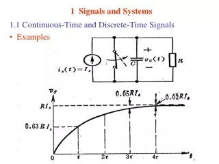
How is a Signal Represented? • Mathematically, signals are represented as a function of one or more independent variables. • Below signal depends on independent variable t with parameters A, ω and . • s= A Sin(ωt+)=A Im{ej(ωt+)} A=Amplitude real ω =angular frequency =phase Sin( ~ )=function ref: http://radarproblems.com/chapters/ch05.dir/ch05pr.dir/c05p1.dir/c05p1.htm
Types of Signal: Analog and digital signals Continuous and Discrete-Time Signals Periodic aperiodic Signal
Types of Signal (contd.) • Unit Step Function u(t) • Ramp function r(t)
System: • A Systemis any physical set of components that takes a signal and transforms it into another signal. • A system can be a simple one that turns a light ON/OFF. Or can be a complex one that does all the computation in a microprocessor. Input signal x(t) Output signal y(t) System ref: http://www.dreamstime.com/royalty-free-stock-image-microchip-circuit-image12540796
Amplifier • An electronic amplifier is a device for increasing the power of a signal. • It does this by taking energy from a power supply and controlling the output to match the input signal shape but with a larger amplitude. • There are various types of amplifier. Amplifier
Time shifter t t • A time shifter system shifts the function f(t) forward or backward by a specific time. • The above system is a forward time shifter. It adds a delay (t0) to the signal. Time shifter f(t) f(t – t0)
Sampler • sampling is the reduction of a continuous-time signal to a discrete-time signal • The sampling frequency must be higher than the frequency of the signal to be sampled. (minimum twice as high) Sampler ref: http://en.wikipedia.org/wiki/Sampling_%28signal_processing%29
Analog to Digital Converter • An analog-to-digital converter(ADC, A/D) is a device that converts a continuous quantity to a discrete time digital representation. • The system that does the opposite is called DAC Analog to Digital DAC ref: http://pictureofgoodelectroniccircuit.blogspot.com/2010/04/phase-and-function-of-analog-signal-or.html
Analog to Digital Conversion • Conversion of Analog to digital is done in two step. • Continuous analog Sampled signal • Sampled signal Quantized digital signal Sampler A/D ref: http://en.wikipedia.org/wiki/Quantization_%28signal_processing%29
Low Pass filter • A low-pass filter is a filter that passes low-frequency signals but attenuates (reduces the amplitude of) signals with frequencies higher than the cutoff frequency. Low Pass Filter ref: http://en.wikipedia.org/wiki/Low-pass_filter
High Pass filter • A high-pass filter (HPF) is a device that passes high frequencies and attenuates (i.e., reduces the amplitude of) frequencies lower than its cutoff frequency. Low Pass Filter ref: http://en.wikipedia.org/wiki/High-pass_filter
Band Pass filter • A band-pass filter is a device that passes frequencies within a certain range and rejects (attenuates) frequencies outside that range. Band Pass Filter ref: http://en.wikipedia.org/wiki/Band-pass_filter
Band Stop filter • band-stop filter or band-rejection filter is a filter that passes most frequencies unaltered, but attenuates those in a specific range to very low levels Band –stop Filter ref: http://en.wikipedia.org/wiki/Band-stop_filter
Signal Processing: • In signal processing, sampling is the reduction of a continuous signal to a discrete signal. • Sampling frequency defines the sampling ‘RESOLUTION’ ref: http://en.wikipedia.org/wiki/Sampling_%28signal_processing%29, http://fourier.eng.hmc.edu/e101/lectures/Sampling_theorem/node1.html
Signal processing: • Fourier Series expansion: The first four Fourier series approximations for a square wave. ref: http://mathworld.wolfram.com/FourierSeries.html
The Fourier Series expansion: • A periodic square wave function ƒ(x) can be expressed with infinite Fourier series expansion. f(x)=sin(x)+ sin(3x)+ sin(5x)+sin(7x)+….. Figure: Construction of a square wave from sinusoids of different frequencies ref: http://www.intmath.com/fourier-series/2-full-range-fourier-series.php
Application: • Communication Applications: Transmission of information (signal) over a channel “Modulation” • Control Applications: Control the speed of fan • Signal Processing Applications: • Speech and audio processing • Multimedia processing • Biological Signal Analysis: • Brain signals (EEG) • Cardiac signals (ECG) • Medical images (x-ray, PET, MRI) ref: http://images.yourdictionary.com/amplitude-modulation, http://en.wikipedia.org/wiki/Amplitude_modulation
Amplitude Modulator • An Amplitude modulator takes a low frequency message signal and a high frequency carrier signal and combines it into a modulated signal of varying amplitude. Amplitude Modulator ref: http://encyclopedia2.thefreedictionary.com/Amplitude+Modulation
Amplitude Demodulator • An Amplitude demodulator takes a modulated signal as input and gives output the original message signal. • The above system is an amplitude demodulator. Its also called ‘envelope detector’. It takes the envelope of the modulated signal to get the information signal. Amplitude Demodulator ref: http://encyclopedia2.thefreedictionary.com/Amplitude+Modulation