Download
1 / 41
410 likes | 546 Vues
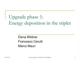
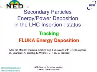
Energy Deposition in the New IRs. Francesco Cerutti , Marco Mauri, Alessio Mereghetti, Ezio Todesco, Elena Wildner. With contributions from: Frank Borgnolutti, Jens Bruer, Alfredo Ferrari, Christine Hoa, Vasilis Vlachoudis and others. AB/ATB and AT/MCS. Outline. Triplet Upgrade

E N D
Energy Deposition in the New IRs Francesco Cerutti, Marco Mauri, Alessio Mereghetti, Ezio Todesco, Elena Wildner With contributions from: Frank Borgnolutti, Jens Bruer, Alfredo Ferrari, Christine Hoa, Vasilis Vlachoudis and others AB/ATB and AT/MCS Review new IRs: Energy Deposition
Outline • Triplet Upgrade • Parametric approach • The Art of Binning • Results • Peak energy deposition • Influence of interconnections • Total loads • Particle Fluences • Conclusions (Part 1) Part Two: A Shielding Option: thick Liner in Q1 Part One: General aspects triplet 110 mm aperture case: power deposition and dose in • TAS • Triplet and corrector package • D1 • TAN • D2 Part Three: Particle fluences in electronics locations • UJ56 • Conclusions (Part 2 and 3) Review new IRs: Energy Deposition
The Triplet, Parametric Approach Actual gradient: 215 T/m Max (cable length) TAS “Symmetric” Q1 Q2a Q2b Q3 IP1 Total Length No Corrector in triplet Half Crossing angle 225 mrad, vertical TAS aperture 55 mm TAS at 19 m, Q1 at 23 m (like actual) Review new IRs: Energy Deposition
The Magnet Cross Section Review new IRs: Energy Deposition
Parameter Space for Parametric Study We get one family of solutions: (Aperture, gradient, length linked) • Q1 Positioned at 23 m from the IP • Gaps between magnets 1.3 m • Impacts the peak in energy deposition we get on the following magnet • Symmetric triplet • All magnets have the same aperture • All magnets have the same gradient • Q1 and Q3 have the same length • Q2 is split in two parts of equal length • Magnets have “costheta” design • Two layers Different from latest “New Triplet” layout, small effect Review new IRs: Energy Deposition
Beam pipe/Beam Screen Dimensioning Cold Bore Tube and Beam Screen act as shielding. For parametric study: get the minimum necessary thicknesses for the different cases chosen • For the Cold Bore Tube (Beam Pipe): • Relation thickness (t) and diameter (D), valid for stainless steel (pressure vessel code, 25 bar ): t = 0.0272D • For the Beam Screen: • Calculations gave the same minimum thickness for all cases (1 mm) • we have used 2 mm (similar as for the previous simulations of the upgraded triplet) Courtesy: G. Kirby, C. Rathjen Review new IRs: Energy Deposition
The Scoring for the Triplet • Peak power in cable (quench) • We make the binning for the scoring so that it corresponds to a minimum volume of equilibrium for the heat transport (cable transverse dimensions, with a length corresponding to the twist pitch of the cable) Length (L) 10 cm (twist pitch) Scoring volume: A*L Transverse area of cable (A) • Total power deposited in the magnets (cryogenics) • The outer diameter of the magnets (cold mass) is the same • The power deposited per meter of magnet • Azimuthal and radial integration of the power in the longitudinal bins • Particle fluence/dose Review new IRs: Energy Deposition
The Bins and the Results • The indicative value 4.3 mW/cm3 (P. Limon, private communication) is valid for Rutherford cable in LHC main magnets, including contingency of a factor of 3! • For other cables and magnet designs,this value has to be revised. Cable bin • For dose calculations (for example cable, insulation and spacers) the bins have to be chosen to get the dose that in reality would damage the bulk material in the object (mechanical and electrical properties) Insulation Review new IRs: Energy Deposition
Peak Power Deposition I 100% increase 140 -> 90 Power Review new IRs: Energy Deposition
Peak Power Deposition II Rescaling longitudinally shows that the pattern is similar! Large effect for Q1 & Q2a Review new IRs: Energy Deposition
The gaps between magnets cause a accumulation of non intercepted particles: peaks at the entrance of magnets (particles from IP collisions) Smaller gaps or shielding of interconnection region interesting Between the Magnets (1) Over all the magnet: Cable 1(red) twice the peaks of cable 2 (blue) => for correctors, for example, use inserts in aperture Magnet1 Magnet2 IP The more smooth pattern is due to the magnetic field (spectrometric effect) Review new IRs: Energy Deposition
Between the Magnets (2) Review new IRs: Energy Deposition
Peak Power Deposition III Large effect in Q1 & Q2a small in Q2b and Q3 Power Review new IRs: Energy Deposition
Total Heat Load Choice of beam screen thickness: redistribution of heat loads Review new IRs: Energy Deposition
Horizontal/Vertical Crossing Can we use our results to scale without re-computing? Review new IRs: Energy Deposition
Particle type Distribution, all 4 Magnets • Fluence scored in the first cable over each magnet. • Interactions from material inside aperture (Beam Screen and Beam pipe) • Smallest (90mm) and largest (140 mm) aperture will be shown Review new IRs: Energy Deposition
Neutron Fluence 90mm/140mm Calculated for 300fb-1 integrated Luminosity Review new IRs: Energy Deposition
Neutron Spectra 90mm/140mm > 1 MeV neutrons most critical for damage Review new IRs: Energy Deposition
The Triplet Layout as of 30/07/08 110 mm aperture Parametric study Review new IRs: Energy Deposition
Summary, General Part (1) • The deposited peak power (quench) decreases with the triplet length. Shorter triplets (smaller apertures) need more shielding (takes more aperture). • The decrease with length is largest in Q1 and Q2, where we also have the highest peaks. • The total heat load on the triplet is decreasing (up to 140 mm at least) with length: between 90 and 130 mm aperture we have 16 % less, including the beam screen. • Pattern of energy deposition is similar for all lengths however not identical for the two insertions (1 and 5). Review new IRs: Energy Deposition
Summary, General Part (2) • The distribution of particle types in Q1 is very similar for 90 and 140 mm. • Spectra similar, ~1.5 time higher fluence for 90 mm than for 140 mm aperture • Great care has to be taken for binning in cables for power deposition (quench) and for longevity of objects (dose calculations), studies ongoing Review new IRs: Energy Deposition
ENERGY DEPOSITION IN THE TAS-D2 REGION FOR A TRIPLET SHIELDING OPTION (THICK LINER IN Q1) power values referred to a 2.5 1034 cm-2 s-1 luminosity time integrated values referred to a 100 fb-1 total luminosity Review new IRs: Energy Deposition
TAS 80 MGy/100fb-1 Dr=1cm x Dj=2o x Dz=2cm scoring grid 45mm TAS aperture -> 110mm triplet coil aperture Review new IRs: Energy Deposition
present LHC (L=L0) 34mm TAS aperture peak power 110 mW/cm3 total power 184 W N.V. Mokhov et al., LHC Project Report 633 TAS 55mm TAS aperture -> 130mm triplet coil aperture peak power 114 mW/cm3 total power 325 W 45mm TAS aperture -> 110mm triplet coil aperture peak power 180 mW/cm3 total power 385 W Review new IRs: Energy Deposition
TRIPLET AND CORRECTOR PACKAGE 110mm coil aperture Q1 Q2a Q2b Q3 10mm thick additional liner 75mm residual aperture Review new IRs: Energy Deposition
TRIPLET AND CORRECTOR PACKAGE horizontal crossing 0.25 m from the IP face 8.05 m from the IP face Review new IRs: Energy Deposition
TRIPLET AND CORRECTOR PACKAGE 1.25 m from the IP face 9.55 m from the IP face vertical crossing Review new IRs: Energy Deposition
TRIPLET AND CORRECTOR PACKAGE horizontal crossing mW/cm3 Dr=2.5mm x Dj=2o x Dz=10cm scoring grid Dr=2.5mm x Dj=60o x Dz=10cm scoring grid Review new IRs: Energy Deposition
TRIPLET AND CORRECTOR PACKAGE vertical crossing mW/cm3 Dr=2.5mm x Dj=2o x Dz=10cm scoring grid Dr=2.5mm x Dj=360o x Dz=10cm scoring grid Review new IRs: Energy Deposition
TRIPLET AND CORRECTOR PACKAGE BS included BS only BS included BS only 101 W +12.9 W in the interconnections (where BS is supposed to continue) in the rest 402 W @ 1.9 K BS included BS only BS included BS only 98 W +11.4 W in the interconnections (where BS is supposed to continue) in the rest 382 W @ 1.9 K Review new IRs: Energy Deposition
D1 180mm coil aperture in the warm bore tube 0.9 2.5 W 0.8 1.4 W Review new IRs: Energy Deposition
(present) TAN 187 MGy/100fb-1 Dx=2.5mm x Dy=2.5mm x Dz=5cm scoring grid inner Cu absorber external tube internal tube 495 15 6 442 32 3 Review new IRs: Energy Deposition
(present) TAN horizontal cuts at beam level Review new IRs: Energy Deposition
(present) D2 in the coils (80 mm aperture) no TCTV, TCTH no TCLP in the coils (80 mm aperture) Review new IRs: Energy Deposition
OVERVIEW mW/cm3 vertical plane Review new IRs: Energy Deposition
OVERVIEW mW/cm3 horizontal plane Review new IRs: Energy Deposition
TRIPLET AND CORRECTOR PACKAGE vertical crossing 130mm coil aperture Q1 Q2a DC Q2b Q3 8/13mm thick additional liner Review new IRs: Energy Deposition
Triplet D1 TAN IP5 TAS UJ57 UJ56 ESTIMATION OF PARTICLE FLUENCES IN ELECTRONICS LOCATIONS Concrete shielding blocks FLUKA model of IR5 (present LHC) courtesy of M. Fuerstner (SC/RP) with contribution of C. Hoa (AT/MCS) Review new IRs: Energy Deposition
>20 MeV HADRON FLUENCE relevant to single event errors vertically averaged over the -60cm < y< 60cm interval (beam axis at y=0) cm-2/100fb-1 In UJ56, after a 2m concrete shielding, the high energy hadron fluence at beam level ranges from 1.3109 up to 1.3 1010 cm-2/100fb-1 Review new IRs: Energy Deposition
UPSTAIRS vertically averaged over the 220cm < y< 420cm interval (beam axis at y=0) cm-2/100fb-1 T. Wijnands Upstairs (sensitive electronics) high energy hadron fluence is in the range 1.2 - 3.6 109 cm-2/100fb-1 Review new IRs: Energy Deposition
CONCLUSIONS • The peak power deposition in the Phase 1 Upgrade triplet SC coils (110-130mm aperture) is expected to be decreased down to the design limit by a 10mm thick stainless steel liner all along the Q1 beam screen, if the interconnection lengths are not increased (unless the liner is extended along the interconnections too). The Q1 liner effectiveness is limited to the first half of the Q2a. • Peaks lie on the crossing plane and change their position (up->down, outer->inner) in the Q2a. • The larger the crossing angle, the higher the peak power density. A magnetic TAS can play a role closing the crossing angle. • ~400 W the triplet toal load + ~100 W in the beam screen (about one half in the Q1 liner). • Peak dose in the coils to be evaluated over a volume relevant to possible damage to the insulator. • A corrector package on the non-IP side of a FDDF triplet is more significantly impacted for vertical crossing (peak at -90o in the transverse plane). • A large aperture SC D1 is not expected to quench. • TAS and TAN thermomechanical stress to be evaluated from the available power deposition maps. • Expected high energy hadron fluence in UJ56 (triplet electronics) is worrying for the present LHC at nominal luminosity (with ideal shielding without holes). Review new IRs: Energy Deposition