Download
1 / 51
590 likes | 1.58k Vues
Learn about the two main types of displays - CRT and LCD, their features including display size, resolution, video RAM requirements, dot pitch, and color displays like CRT and LCDs. Explore how CRT and LCD displays operate and differences in video interfaces like composite video and RGB.

E N D
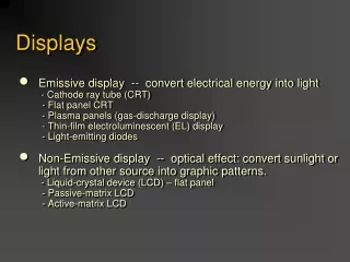
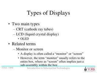
Types of Displays • Two main types • CRT (cathode ray tubes) • LCD (liquid crystal display) • OLED • Related terms • Monitor or screen • A display is often called a “monitor” or “screen” • However, the term “monitor” usually refers to the entire box, where as “screen” often implies just a sub-assembly within the box
Pixels • A Pixel is a “picture element” • a single point in a graphic image • A graphics display is divided into thousands (or millions) of pixels arranged in rows and columns • The pixels are so close together, they appear connected • The number of bits used to represent each pixel determines how many colours or shades of grey can be represented • For a B&W (black and white) monitor, each pixel is represented by 1 bit • With 8 bits per pixel, a monitor can display 256 shades or grey or 256 colours (Note: 28 = 256)
15” Display Size • Usually specified in “inches” • Value cited is the diagonal dimension of the raster -- the viewable area of the display • E.g., a 15” monitor
Resolution • Resolution is the number of pixels on a screen display • Usually cited as n by m • n is the number of pixels across the screen • m is the number of pixels down the screen • Typical resolutions range from… • 640 by 480 (low end), to • 1,600 by 1,200 (high end)
Video RAM Requirements • Total number of pixels is n m • Examples • 640 480 = 307,200 pixels • 1,600 1,200 = 1,920,000 pixels • Video RAM required equals total number of pixels times the number of bits/pixel • Examples • 640 480 8 = 2,457,600 bits = 307,200 bytes = 300 Kbytes • 1,600 1,200 24 = 46,080,000 bits = 5,760,000 bytes = 5,625 Kbytes = 5.49 Mbytes
Video RAM (KB) Per Image See previous slide for calculations
Dot Pitch • Dot pitch is a measure of the diagonal distance between phosphor dots (pixels) on a display screen • One of the principal characteristics that determines the quality of a display • The lower the number, the crisper the image • Cited in mm (millimeters) • Typical values range from 0.15 mm to 0.30 mm • Note • Dot pitch, as specified, is the capability of the display • For a particular image, dot pitch can be calculated as…
Dot pitch = 15 / 800 inches = 0.01875 inches = 0.01875 / 0.039 mm = 0.481 mm Notes: Z 480 • Z = (6402 + 4802)1/2 = 800 • 1 mm = 0.039 inch 640 Dot Pitch Image Example • Q: What is the dot pitch of an image displayed on a 15” monitor with a resolution of 640 by 480? • A:
Dot Pitch Illustrated Pixel 0.481 mm
Dot Pitch Image Table Note: Dot pitch figures in mm (millimeters)
Colour Displays • CRT displays • each pixel is composed of three superimposed dots: red, green, and blue • Hence, RGB display • The three dots are created by three separate beams • Ideally, the three dots should converge at the same point, however, in practice there is a small amount of convergence error, and this makes the pixels appear fuzzy • LCDs • Colour is created by filtering/blocking different frequencies of light
CRT Display Rev: Fig 9.21 pg 267 ff
Operation of a CRT Display • A CRT display contains a vacuum tube • At one end are three electron guns, one each for red, green, and blue • At the other end is a screen with a phosphorous coating • The three electron guns fire electrons at the screen and excite a layer of phosphor • Depending on the beam, the phosphor glows, either red, green, or blue
Color Transformation Table G B Figure 9.17 Use of a color transformation table
Figure 9.20 Display example: (a) desired display, (b) video memory contents, (c) color palette table, (d) color signals
Operation of an LCD • Two sheets of polarizing material with a liquid crystal solution between them • An electric current passed through the liquid causes the crystals to align so that light cannot pass through them • Each crystal, therefore, acts like a shutter, either allowing light to pass through or blocking the light
Active-Matrix Display • A type of liquid crystal display in which the image is refreshed more frequently than in conventional (passive matrix) displays • Most common type of active-matrix display is known as TFT (thin-film transistor) • The terms active matrix and TFT are used interchangeably
Video Interfaces (1 of 2) • Composite video • Definition: a video interface in which all the colour and sync information is contained in one signal • Contrast with RGB • TVs in North America use composite video • RGB (Red, Green, Blue) • Definition: a video interface in which the red, green, and blue signals, and the horizontal and vertical sync signals, are separate • Computer monitors use RGB
Video Interfaces (2 of 2) • S-video • A technology for transmitting video signals over a cable by dividing the video information into two separate signals: one for colour (chrominance, C), and one for brightness (luminance, Y) • Also called Y/C video • Televisions (internally) are designed for separate luminance and chrominance signals • Computer monitors are designed for separate red, green, and blue signals
RGB Video Standards • A variety of standards exist for delivering RGB signals to a video display monitor • Developed and consolidated by VESA (Video Electronics Standards Association) • Examples • VGA – video graphics adapter • SVGA – super-VGA • XGA – extended graphics adapter
VGA/SVGA/XGA Pinouts DE15 connector
S-video Pinouts 4-pin mini-DIN connector
Plan • Printers • Scanners
Impact Printers • Main types: • Impact • Laser • Ink jet
Impact vs. Non-Impact • Impact printers physically transfer a dot or shape to the paper • Include dot-matrix, belt, & solid line printers • Non-impact printers spray or lay down the image • Impact printers remain important because they can print multi-part forms(eg: carbon or NCR copies)
Printers • Main types: • Dot matrix (sample impact) • Laser • Ink jet
How it works( Impact Type Dot-Matrix ) A print-head moves back-and-forth in front of forms (paper) on which characters or graphic images are transferred. The print-head contains numerous wires, typically from 9 to 24. Each wire is part of a solenoid-like unit. An electrical pulse applied to the solenoid creates a magnetic field which forces the wire to move briefly forward then backward. As the wire moves forward, it strikes a print ribbon containing ink. The impact transfers an ink dot to the paper. The paper is supported from behind by a platen. (a hard flat piece)
One print wire Side view Dot Matrix Print Head Print wires (e.g., 12) Front view
Paper Printwire Platen Ribbon Side view Front view Dot Matrix Impact Printing Paper Side view
Specifications • cps • characters per second • Varies by quality of print (e.g., draft vs. final (NLQ)) • lpm • lines per minute (related to cps) • Forms • Maximum number of layers of paper that can by printed simultaneously • Specified as n-part forms (e.g., 4-part forms) • mtbf • Mean time between failure (e.g., 6000 hours)
Dot Matrix Printer Example Specifications • 800 cps • 400 lpm • 6-part forms (max) FormsMaster 8000 by Printek, Inc. http://www.printek.com
Printers • Main types: • Dot matrix • Laser • Ink jet
Laser Photosensitivedrum Spinningmirror Operation of a Laser Printer • Four steps • A laser is fired in correspondence to the dots to be printed. A spinning mirror causes the dots to be fanned out across the drum. The drum is photosensitive. As a result of the laser light, the drum becomes electrically charged wherever a dot is to be printed. • The drum rotates to the next line, usually 1000th or 1600th of an inch.
Top View of Rotating Mirror Drum Rotating Mirror: This one has eight faces Laser light source
Operation of a Laser Printer 2. As the drum continues to rotate, the charged part of the drum passes through a tank of black powder called toner. Toner sticks to the drum wherever the charge is present. Thus, the pattern of toner on the drum matches the image. Toner
Chargewire Paper Operation of a Laser Printer 3. A sheet of paper is fed toward the drum. A charge wire coats the paper with electrical charges. When the paper contacts the drum, it picks up the toner from the drum
Fusingsystem Coronawire Operation of a Laser Printer 4. As the paper rolls from the drum, it passes over a heat and pressure area known as the fusing system. The fusing system melts the toner to the paper. The printed page then exits the printer.As the same time, the surface of the drum passes over another wire, called a corona wire. This wire resets the charge on the drum, to ready it for the next page.
Specifications • ppm • Pages per minute • Typically 4-10 ppm • dpi • Dots per inch • Typically 600-1200 dpi
Laser Printer Example Laserjet 5000 Series from Hewlett Packard Co. (http://www.hp.com)
Printers • Main types: • Dot matrix • Laser • Ink jet
Background • Inkjet technology was developed in the 1960s • First commercialized by IBM in 1976 with the 6640 printer • Cannon and Hewlett Packard developed similar technology • Also called bubble jet
How it works Characters and graphics are 'painted‘ line by line to from a pattern of dots as a print head scans horizontally across the paper. An ink-filled print cartridge is attached to the inkjet's print head. The print head contains 50 or more ink-filled chambers, each attached to a nozzle. An electrical pulse flows through thin resistors at the bottom of each chamber. When current flows through a resistor, the resistor heats a thin layer of ink at the bottom of the chamber to more than 900 degrees Fahrenheit for several millionths of a second . The ink boils and forms a bubble of vapour. As the vapour bubble expands, it pushes ink through the nozzle to form a droplet at the tip of the nozzle. The droplet sprays onto the paper. The volume of the ejected ink is about one millionth that of a drop of water from an eye-dropper. A typical character is formed by an array of these drops 20 across and 20 high. As the resistor cools, the bubble collapses. The resulting suction pulls fresh ink from the attached reservoir into the firing chamber.
Plan • Printers • Scanners
How it works A scanner works by digitizing an image. A scanning mechanism consists of a light source and a row of light sensors. As light is reflected from individual points on the page, it is received by the light sensors and translated to digital signals that correspond to the brightness of each point. Colour filters can be used to produce colour images, either by providing multiple sensors or by scanning the image three times with a separate colour filter for each pass. The resolution of scanners is similar to that of printers, approximately 300-600 dpi (dots per inch).
Scanners • Three main types • Flatbed • Sheet-fed • Handheld
Sheet-fed Scanner Example OfficeJet Series 700 from Hewlett Packard Co (http://www.hp.com)