Path Based Buffer Insertion
Path Based Buffer Insertion. C. N. Sze, Charles J. Alpert†, Jiang Hu and Weiping Shi DAC 2005, June 13–17, 2005, Anaheim, California, USA. Outline. Introduction Problem Formulation Net Based Buffer Insertion Path Based Buffer Insertion

Path Based Buffer Insertion
E N D
Presentation Transcript
Path Based Buffer Insertion C. N. Sze, Charles J. Alpert†, Jiang Hu and Weiping Shi DAC 2005, June 13–17, 2005, Anaheim, California, USA.
Outline • Introduction • Problem Formulation • Net Based Buffer Insertion • Path Based Buffer Insertion • Path Based Buffer Insertion And Simultaneous Gate Sizing • Experimental Results • Conclusion
Introduction • Buffer insertion is an effective technique for reducing interconnect delay. • Most of the previous works on buffer insertion are net based, i.e., buffer insertion is performed on one net after another individually.
Problem Formulation • We represent a combinational circuit as a Directed Acyclic Graph (DAG) G = (V,E).
Problem Formulation • Elmore delay D(e) =R(e)[C(e)/2 + C(vj)] D(vj) = K(b) + R(b) .C(vj) e: edge (vi, vj) R(e): resistance of e C(e): capacitance of e C(vj): downstream capacitance at vj K(b): intrinsic delay of buffer b R(b): driving resistance of buffer b
Problem Formulation • In this paper, the size of each gate is selected from the set S = {x1, ...,xn}. • Each primary input is annotated with a user-defined arrival time while each primary output a required arrival time.
Problem Formulation • Signal slew rate is also considered in the path based buffer insertion algorithm. propagation_slew = ln9 · Elmore delay launching_slew : the launching slew rate at the driving end of the wire
Problem Formulation • The paper abstract the routing tree of the circuit and ignore all the details (i.e., Steiner node and interconnect tree structure, etc.) within the routing tree. • The vertices only represent PI/PO of the circuit and input/output pins of modules while edges only for input-to-output paths within a module.
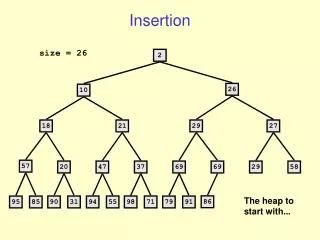
Net Based Buffer Insertion • Static timing analysis (STA) and obtain the RAT and AT at every vertex • Perform buffer insertion for a routing tree with the AT and RAT obtained from STA • Update STA results (of the fanin/fanout cone of the buffered routing tree) and perform buffer insertion for the next routing tree
Net Based Buffer Insertion • STA is usually not buffer aware so the timing estimation at the first iterations are inaccurate and the circuit is very timing critical. Hence, the first processed nets tend to over-consume buffer resources. • Earlier buffering decision may have degraded the quality of the whole buffering process, which cannot be improved in latter iterations.
Path Based Buffer Insertion • Buffer Aware Static Timing Analysis • With buffer aware STA, early buffering step will not over-consume buffer resource which trap the overall solution into a local optimum.
Path Based Buffer Insertion • Path Based Buffer Insertion • Find k most critical paths • If the list of paths are overlapping with each other, we delete the common vertices from the less-critical path and cut it into different distinct paths.
Path Based Buffer Insertion • For example, if the 3 most critical paths are {b,g,i,r} , {a,f,i,j,o,s} , {c,k,o,s}, after removing common vertices, the list of distinct paths becomes {b,g,i,r} , {a,f} , {j,o,s} , {c,k}.
Path Based Buffer Insertion • For each distinct path merge all routing trees along the path • The merged routing tree on the path {b,g, i, r}consists of three sinks l, j, r rooted at b. g and i are merged into one buffer location with a special buffer bsaccording to input-to-output path of M1 (The delay model of a buffer is similar to that of an input-to-output path of a module).
Path Based Buffer Insertion • van Ginneken algorithm is applied to the merged routing tree. • After all paths have been processed, there may exist some routing trees in which no buffer insertion has been performed. They are all comparatively non-critical and net based buffer insertion can be carried out for each of those nets.
Path Based Buffer Insertion • Off-Path Required Arrival Time Estimation • Since the PBBI algorithm performs buffer insertion in a path-bypath basis, the buffering solution may violate the timing constraints.
Path Based Buffer Insertion • Assume that a is a PI vertex and z is a PO vertex and the algorithm processes the path p1 = {a → g→ h → p→ r → z} prior to another path p2 = {i → q}.
Path Based Buffer Insertion • A buffering solution for the whole circuit with minimum cost tends to spread the “useful slack” to each RT(si). • Note that ATBs1 = ATs1 and RATBtk = RATtk . Ideally, ATBsi = RATBsi since the solution B would consume “useful slack” completely. (useful slack: RATsi-ATsi)
Path Based Buffer Insertion • Theorem 1 If the “useful slack” evenly distributes to every RT(si) for i = 1, ...,k in a manner that (delay_to_POBsi/ delay_to_POsi) is a constant among all si, then delay_to_POBsi=RATBtk −RATBsi , delay_to_POsi=RATtk − RATsi
Path Based Buffer Insertion And Simultaneous Gate Sizing • Sizing up a gate reduces the output resistance and so the delay is reduced. • At the same time, the input capacitance increases which in turn raises the delay of upstream interconnect.
Path Based Buffer Insertion And Simultaneous Gate Sizing • Gate Sizing at the Sinks • If the sink vertex is not a PO, and if the module at the sink is not sized previously, we perform gate sizing for the module at the sink. • We perform gate sizing at all sinks of the merged routing tree while we apply VGDP. • We propagate n solutions (n is the total number of different gate sizes), each of which have a scaled load capacitance, the gate size as its cost, and an modified required arrival time RAT’s(xi).
Path Based Buffer Insertion And Simultaneous Gate Sizing • For simplicity, we assume that there is a linear relationship between the delay change (RAT’s(xi)−RATs) and the change in resistance (Ri−R0). Rb : output resistance of the buffer Cb : input capacitance of the buffer R0 : original output resistance of the gate Ri : output resistance of the sized gate
Experimental Results Table 2: Comparison of net based and path based buffer insertion
Experimental Results Table 3: Comparison of net based and path based buffer insertion considering buffer blockages
Experimental Results ΔG : total size change in all gates Δarea : B cost + ΔG Table 4: Comparison of net based and path based buffer insertion considering gate sizing
Conclusion • This approach can obtain a better buffer usage efficiency due to its global view. • This is the first work on path based buffer insertion. • The speed of this approach is much slower than net based buffer insertion.