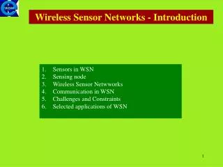
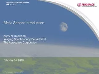
Mako Sensor Introduction
Mako Sensor Introduction. Kerry N. Buckland Imaging Spectroscopy Department The Aerospace Corporation. February 14, 2013. Mako Sensor (1 of 6).

Mako Sensor Introduction
E N D
Presentation Transcript
Mako Sensor Introduction Kerry N. BucklandImaging Spectroscopy DepartmentThe Aerospace Corporation February 14, 2013
Mako Sensor (1 of 6) • Mako is a LWIR HSI whisk-broom scanner designed to extend the technology forward from previous instruments designed and built by The Aerospace Corporation • Innovative spectrometer design (f/1.25) results in 20x light-gathering power of earlier sensors • 1995 SEBASS (Spatially Enhanced Broadband Array Spectrograph System) • 1998 SHARP (SEBASS High Altitude Research Project) • 2001 – 2003 other sensors (2) • 2003 GBSS (Ground Based SHARP Sensor) • 2004 WAHOO • 2004 – 2008 other sensors (4) • 2010 Mako • Mako is an asset of The Aerospace Corporation • Developed under a Corporate Research Initiative (CRI) • No data collection restrictions (except airspace considerations) • Available for use • Scientific Investigations • Phenomenology Studies • Government and Commercial Projects
Mako Sensor (2 of 6) • Mako uses a DRS Si:As Blocked Impurity Band 128x128 FPA • 75 m pixels • Cooled to ~10K using LHe • 99.93% operable • 4 kHz max frame rate; 16 output taps • Spectrometer based on Dyson lens and concave grating • Low distortions (“smile” and “keystone”) at fast f-numbers • Mako is an f/1.25 system • Cooled optics (using LHe blow-off) for improved sensitivity and increased dynamic range • 48-hour dewar hold time
Mako Sensor (3 of 6) • Mako uses a commercial 3-axis stabilization mount • Intergraph Z/I mount • High frequency jitter removed by physical vibration dampeners • Low frequency jitter removed by active control • Stabilizes up to ±5° range in pitch and roll • Up to ±12° yaw offset can be accommodated • Sensor attitude measured with Litton LN-100G INS and KVH DSP-3000 fiber-optic gyros (x3) • Pixel geolocation accuracy is <10 meters from 12,000 ft AGL • Using differential GPS • Gimbal mirror pitch control provides additional capability • Bi-directional whisking • High Sensitivity scans (“stare” mode)
Mako Sensor (4 of 6) LHe Cryostat Inertial Navigation System Inertial Stabilization Mount FPA Electronics Dyson Spectrometer F/1.25 Scan mirror/motor Re-imager Calibration Source (2) Telescope
Mako Sensor (6 of 6) • Data Collection Modes • Large-Area Coverage Mode • 20 km2 / min (2m GSD) from 12500 ft AGL • High Sensitivity Mode • Noise reduction achieved through increased coadds • Done at the expense of Large-Area Coverage • Time on station spent collecting smaller ground areas with longer integration times • Remote Infrared Hyperspectral Applications • Mineral exploration • Emissions (chemical plumes) • Geothermal site characterization • Environmental assessments • Urban surveys • Precision thermal mapping
Mako Sensor Operations Sensor installation onboard DeHavilland DHC-6 Twin Otter Air Crew (typical) Pilots (2) Sensor Operator Navigator (communications to pilots/ground) Analyst (onboard processing)
Large-Area Coverage using Whisk Broom Scans Mako • Mako whisk broom scan is up to 27x wider than SEBASS push broom scan (for equivalent GSD) • Scanning of pitch compensates for aircraft motion during whisk acquisition
Mako Large-Area Coverage Example (full extent) 33 km LAX Cube #140 Cube #1 Los Angeles, California; Detail View (South of LAX) Shown on Next Slide ~11 min data collection
Mako Large-Area Coverage Example (detail) 5.4 km 7.1 km Quickbird – True Color Image (south of LAX) Mako – 10.6 mm Thermal Image (~1.8 min data collection)
Mako Large-Area Coverage Example (Imperial Valley) False-color LWIR radiance mosaic (2m GSD) acquired in a single 4 min pass over an area of exposed complex geological structure in California’s Imperial Valley. The area acquired is ~90 km2 (cf. SEBASS ~3.5 hours).
Detection Example (NH3) Session: 110824_230208_WS315 34 whisks Location: Redondo Beach, CA Plume Sources (4): Power Plant (1 and 2) “Ammonia Slip” NOX Reduction Plume Length ~5 miles Note additional (3 and 4) plume sources downwind from primary sources 3 1 2 4
Information For additional information contact: The Aerospace Corporation Imaging Spectroscopy Department 2310 E. El Segundo Blvd. El Segundo, CA 90245-4609 POC Kerry N. Buckland, Ph.D. M2 / 272 kerry.n.buckland@aero.org 310-336-0254 All trademarks, trade names, and service marks are the property of their respective owners.