Solid State Physics (1) Phys3710 Crystal Structure 3 Lecture 3
Solid State Physics (1) Phys3710 Crystal Structure 3 Lecture 3. Department of Physics. Dr Mazen Alshaaer Second semester 2013/2014. Ref.: Prof. Charles W. Myles, Department of Physics, Texas Tech University.

Solid State Physics (1) Phys3710 Crystal Structure 3 Lecture 3
E N D
Presentation Transcript
Solid State Physics (1) Phys3710 Crystal Structure 3 Lecture 3 Department of Physics Dr Mazen Alshaaer Second semester 2013/2014 Ref.: Prof. Charles W. Myles, Department of Physics, Texas Tech University
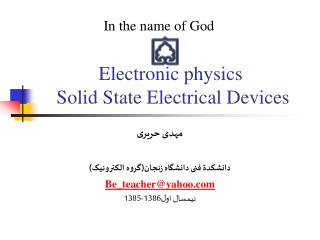
A simple, geometric method to construct aPrimitive Cell is called the Wigner-Seitz Method. The procedure is: Wigner-Seitz Methodto Construct a Primitive Cell • Choose a starting lattice point. • Draw lines to connect that point to its nearest neighbors. • At the mid-point & normal to these lines, draw new lines. • The volume enclosed is called a Wigner-Seitz cell. Illustration for the 2 dimensional parallelogram lattice. 2
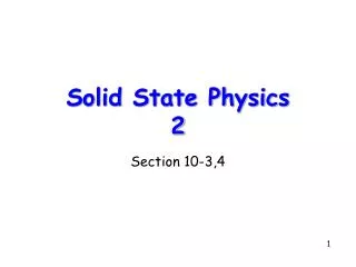
3 Dimensional Wigner-Seitz Cells Face Centered Cubic Wigner-Seitz Cell Body Centered Cubic Wigner-Seitz Cell 3
Basic definitions – Lattice sites Define basic terms and give examples of each: • Points (atomic positions) • Vectors (defines a particular direction - plane normal) • Miller Indices (defines a particular plane) • relation to diffraction • 3-index for cubic and 4-index notation for HCP
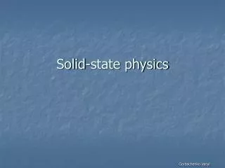
Lattice Sites in a Cubic Unit Cell1) To define a point within a unit cell…. • The standard notation is shown in the figure. It is understood that all distances are in units of the cubic lattice constant a, which is the length of a cube edge for the material of interest.
2) Directions in a Crystal: Standard Notation • See FigureChoose an origin, O. This choice is arbitrary, because every lattice point has identical symmetry. Then, consider the lattice vector joining O to any point in space, say point T in the figure. As we’ve seen, this vector can be written T = n1a1 + n2a2 + n3a3 [111] direction • In order to distinguish aLattice Directionfrom aLattice Point,(n1n2n3),the 3 integers are enclosed in square brackets[ ...]instead of parentheses(...), which are reserved to indicate a Lattice Point. In direction[n1n2n3], n1n2n3are the smallest integerspossible for therelative ratios.
c b a 5. Designate negative numbers by a bar • Pronounced “bar 1”, “bar 1”, “zero” direction. 6. “Family” of [110] directions is designated as <110>. DIRECTIONS will help define PLANES (Miller Indices or plane normal). Directions in a Crystal Procedure: • Any line (or vector direction) is specified by 2 points. • The first point is, typically, at the origin (000). • Determine length of vector projection in each of 3 axes in units (or fractions) of a, b, and c. • X (a), Y(b), Z(c) 1 1 0 • Multiply or divide by a common factor to reduce the lengths to the smallest integer values, u v w. • Enclose in square brackets: [u v w]: [110] direction.
210 Examples X = 1 , Y = ½ , Z = 0 [1 ½ 0] [2 1 0] X = ½ , Y = ½ , Z = 1 [½ ½ 1] [1 1 2]
When we write the direction [n1n2n3] depending on the origin, negative directions are written as R = n1a1 + n2a2 + n3a3 To specify the direction, the smallest possible integers must be used. Z direction - X direction (origin) O - Ydirection X direction - Z direction Negative Directions Y direction 9
Examples of Crystal Directions X = 1 , Y = 0 , Z = 0 [1 0 0] X = -1 , Y = -1 , Z = 0 [110] 10
Examples A vector can be moved to the origin. X =-1 , Y = 1 , Z = -1/6 [-1 1 -1/6] [6 6 1] 11
Within a crystal lattice it is possible to identify sets of equally spaced parallel planes. These are called lattice planes. In the figure, the density of lattice points on each plane of a set is the same & all lattice points are contained on each set of planes. b b a a Crystal Planes The set of planes for a 2D lattice. 12
Miller Indices are a symbolic vector representation for the orientation of an atomic plane in a crystal lattice & are defined as the reciprocals of the fractional intercepts which the plane makes with the crystallographic axes. To find the Miller indices of a plane, take the following steps: Determine the intercepts of the plane along each of the three crystallographic directions. Take the reciprocals of the intercepts. If fractions result, multiply each by the denominator of the smallest fraction. Miller Indices 13
(1,0,0) Example 1 14
(0,1,0) (1,0,0) Example 2 15
(0,0,1) (0,1,0) (1,0,0) Example 3 16
(0,1,0) (1/2, 0, 0) Example 4 17
Example 5 18
Example 6 19
Plane intercepts axes at [2,3,3] 2 Reciprocal numbers are: 2 3 (111) (200) (100) (100) (110) Examples of Miller Indices Miller Indices of the plane: (2,3,3) Indices of the direction:[2,3,3] 20
Example 7 22
Indices of a Family of Planes Given any plane in a lattice, there is a infinite set of parallel lattice planes (or family of planes) that are equally spaced from each other. • One of the planes in any family always passes through the origin. The Miller indices (hkl) usually refer to the plane that is nearest to the origin without passing through it. • You must always shift the origin or move the plane parallel, otherwise a Miller index integer is 1/0, i.e.,∞! • Sometimes (hkl) will be used to refer to any other plane in the family, or to the family taken together. • Importantly, the Miller indices (hkl) is the same vector as the plane normal!
Sometimes. when the unit cell has rotational symmetry, several nonparallel planes may be equivalent by virtue of this symmetry, in which case it is convenient to lump all these planes in the same Miller Indices, but with curly brackets. Indices of a Family of Planes Thus indices {h,k,l} represent all the planes equivalent to the plane (hkl) through rotational symmetry. 24
This results in the fact that, in 3 dimensions, there are only 7 different shapes of unit cell which can be stacked together to completely fill all space without overlapping. This gives the 7 crystal systems, in which all crystal structures can be classified. These are: The Cubic Crystal System (SC, BCC, FCC) The Hexagonal Crystal System (S) The Triclinic Crystal System (S) The Monoclinic Crystal System (S, Base-C) The Orthorhombic Crystal System (S, Base-C, BC, FC) The Tetragonal Crystal System (S, BC) The Trigonal (orRhombohedral) Crystal System (S) Classification of Crystal Structures • Crystallographers showed a long time ago that, in 3 Dimensions, there are 14 BRAVAIS LATTICES+7 CRYSTAL SYSTEMS 25
For a Bravais Lattice, The Coordinatıon Number The number of lattice points closest to a given point(the number of nearest-neighbors of each point). Because of lattice periodicity, all points have the same number of nearest neighbors or coordination number.(That is, the coordination number is intrinsic to the lattice.) Examples Simple Cubic (SC)coordination number = 6 Body-Centered Cubic coordination number = 8 Face-Centered Cubic coordination number = 12 Coordination Number Crystal Structure 27
For a Bravais Lattice, The Atomic Packing Factor (APF)the volume of the atoms within the unit cell divided by the volume of the unit cell. Atomic Packing Factor(or Atomic Packing Fraction) • When calculating the APF, the volume of the atoms in the unit cell is calculated AS IF each atom was a hard sphere, centered on the lattice point & large enough to just touch the nearest-neighbor sphere. • Of course, from Quantum Mechanics, we know that this is very unrealistic for any atom!!
1- CUBIC CRYSTAL SYSTEMS 3 Common Unit Cells with Cubic Symmetry Simple Cubic Body Centered Cubic Face Centered Cubic (SC) (BCC) (FCC)
b c a a- The Simple Cubic (SC) Lattice • The SC Latticehas one lattice point in its unit cell, so it’s unit cell is a primitive cell. • In the unit cell shown on the left, the atoms at the corners are cut because only a portion (in this case 1/8) “belongs” to that cell. The rest of the atom “belongs” to neighboring cells. • The Coordinatination Number of the SC Lattice = 6. 31
Simple Cubic (SC) Lattice Atomic Packing Factor 32
b- The Body Centered Cubic (BCC) Lattice • The BCC Lattice has two lattice points per unit cell so the BCC unit cell is a non-primitive cell. • Every BCC lattice point has 8 nearest- neighbors. So (in the hard sphere model) each atom is in contact with its neighbors only along the body-diagonal directions. • Many metals(Fe,Li,Na..etc),including the alkalis and several transition elements have the BCC structure. c b a 33
2 (0,433a) Body Centered Cubic (BCC) Lattice Atomic Packing Factor Crystal Structure 35
In the FCC Lattice there are atoms at the corners of the unit cell and at the center of each face. The FCC unit cell has 4 atoms so it is a non-primitive cell. Every FCC Lattice point has 12 nearest-neighbors. Many common metals(Cu,Ni,Pb..etc) crystallize in the FCC structure. c- The Face Centered Cubic (FCC) Lattice Crystal Structure 37
0,74 FCC Face Centered Cubic (FCC) Lattice Atomic Packing Factor 4 (0,353a) Crystal Structure 39
FCC & BCC: Conventional Cells With a Basis • Alternatively, the FCC lattice can be viewed in terms of a conventional unit cell with a 4-point basis. • Similarly, the BCC lattice can be viewed in terms of a conventional unit cell with a 2- point basis.
Comparison of the 3 Cubic Lattice Systems Unit Cell Contents Counting the number of atoms within the unit cell Atom PositionShared Between: Each atom counts: corner 8 cells 1/8 face center 2 cells 1/2 body center 1 cell 1 edge center 2 cells 1/2 Lattice TypeAtoms per Cell P (Primitive) 1 [= 8 1/8] I (Body Centered) 2 [= (8 1/8) + (1 1)] F (Face Centered) 4 [= (8 1/8) + (6 1/2)] C (Side Centered) 2 [= (8 1/8) + (2 1/2)] Crystal Structure 42
2- HEXAGONAL CRYSTAL SYSTEMS In a Hexagonal Crystal System, three equal coplanar axes intersect at an angle of 60°, and another axis is perpendicular to the others and of a different length. The atoms are all the same. Crystal Structure
This is another structure that is common, particularly in metals. In addition to the two layers of atoms which form the base and the upper face of the hexagon, there is also an intervening layer of atoms arranged such that each of these atoms rest over a depression between three atoms in the base. Hexagonal Close Packed (HCP) Lattice Crystal Structure 46
Hexagonal Close Packed (HCP) Lattice The HCP lattice is not a Bravais lattice, because orientation of the environment of a point varies from layer to layer along the c-axis.
Hexagonal Close Packed (HCP) Lattice Bravais Lattice : Hexagonal Lattice He, Be, Mg, Hf, Re (Group II elements) ABABAB Type of Stacking a = b Angle between a & b = 120° c = 1.633a, basis: (0,0,0) (2/3a ,1/3a,1/2c) Crystal Structure 48
A A A A A B B B B C C C A A A A A A A B B B B B C C C C A A A A A A A A B B B B C C C B B A A A A A A A Comments on Close Packing Close pack Sequence AAAA… - simple cubic Sequence ABABAB.. • hexagonal close pack Sequence ABAB… - body centeredcubic Sequence ABCABCAB.. -face centered cubic close pack Crystal Structure 50