Download
1 / 1
70 likes | 330 Vues
ATLAST-9.2: A Deployable Large Aperture UVOIR Space Telescope.

E N D
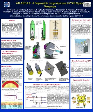
ATLAST-9.2: A Deployable Large Aperture UVOIR Space Telescope W. Oegerle1, L. Feinberg1, L. Purves1, T. Hyde1, H. Thronson1, J. Townsend1, M. Postman2, M. Bolcar1, J. Budinoff1, B. Dean1, M. Clampin1, D. Ebbets3, Q. Gong1, T. Gull1, J. Howard1, A. Jones1, R. Lyon1, B. Pasquale1, C. Perrygo4, S. Smith1, P. Thompson1, B. Woodgate1 and the ATLAST Concept Study Team (1NASA/Goddard Space Flight Center, 2Space Telescope Science Institute, 3Ball Aerospace, 4SGT/GSFC) Sunshield and Stray Light A planar sunshield plus a central primary mirror baffle is sufficient to limit stray light to less than 10% of the zodiacal sky brightness while also eliminating “rogue path” light that would otherwise skirt around the secondary mirror. The deployed sunshield consists of four layers of opaque Kapton film with a simple flat square shape, 28 m on a side. To ease manufacture, integration and test (I&T), and stowage procedures, each of the four layers is subdivided into four quadrants that are connected during I&T so that each deployed layer is continuous. Four 18-meter booms extend in a cruciform configuration to deploy the membranes. Abstract We present the results of a study of a deployable version of the Advanced Technology Large Aperture Space Telescope (ATLAST) that could be launched on an Evolved Expendable Launch Vehicle (EELV). The observatory retains significant heritage from JWST, thereby taking advantage of technologies and engineering already developed for that mission. At the same time, we have identified several design changes to the JWST architecture, some of which are required due to the demanding wavefront quality required for diffraction limited imaging at 500 nm. ATLAST-9.2 (folded) inside Delta IV Heavy fairing Four layer sunshield (corner) Drive with 4 cables Launch Vehicle, Orbit ATLAST fits into a modest upgrade to the Delta IV Heavy, which will have a 6.5 m (outer diameter) fairing, and the ability to put 15,800-18,000 kg into SEL2 orbit (ref: www.ulalaunch.com). The launch trajectory provides direct injection to a halo or Lissajou orbit with no eclipses by the Earth over ten years. Delta-IV Heavy with 6.5m diameter x 29.5 m payload fairing Deployed OTA Folded OTA rear view, showing instruments (colored boxes) The Optical Telescope Assembly (OTA) The OTA is a 9.2m segmented mirror consisting of 36 hexagonal Ultra-Low Expansion (ULE) glass mirrors. The mirrors are 1.315m in size (flat-to-flat) with areal density of ~20 kg/m2. The architecture retains much of its heritage from JWST. The OTA is operated at room temperature and is thermally controlled using heaters on its backplane. 18 m boom Gimbaled mounting of OTA The OTA is mounted on a multi-gimbal arm that provides OTA pitch motion, roll about the OTA line of sight, and center of mass trim for solar torque control while allowing the spacecraft and sunshield attitude relative to the Sun to remain fixed. This enables a very large field of regard with allowed pointing from 45 to 180° from the sun, permitting the use of an external occulter (starshade) for high contrast imaging of exoplanets. An active isolation system between the arm and OTA isolates spacecraft disturbances and, using the FGS sensor, provides a total image motion (ie. jitter) of ~1 milli-arcsec. Deployment Sequence Optical Design The optical design provides a Three Mirror Anastigmat (TMA) channel for wide FOV instruments and a Cassegrain channel that minimizes reflections in the UV contains coronagraphic instruments for observing exoplanets. The primary mirror is fast (f/1.25) to minimize length of the OTA. Primary and secondary mirrors are coated with Al+MgF2 for UV response. All optics in the TMA channel and in the exoplanet instruments with > 500 nm are coated with protected silver. The design is diffraction-limited at = 500 nm over an 8 x 20 arcmin FOV. The wavefront error map for the TMA channel is shown below The FOV in the Cass channel is ~ 1 arcmin Sunshield deployed (looking from sun side; S/C bus Visible) Gimbal arm unstowed and OTA deployed (dark side of sunshield) Deploy solar array and comm antenna After fairing separation Spacecraft & Servicing The spacecraft bus provides coarse attitude control, propulsion, power, communication (Ka band) and data handling modeled after JWST, but employs a modular architecture (shown below) that allows servicing and reduces risk during I&T. Each bay in the octagonal S/C bus is easily accessible and removable. Refueling of propellant tanks could also be done robotically during servicing to extend observatory life. All instruments are modular and replaceable on orbit using an HST-derived rail and kinematic latching systems. Modular spacecraft bus Wavefront Sensing & Control (WFS&C) The core technologies for WFS&C are similar to those employed on JWST, but will run in real-time without ground intervention. A schematic of one of the combined Fine guidance sensor (FGS) and WFS sensors is shown in Figure 1. Light from the OTA is fed to the FGS/WFS via a pick-off mirror. A bi-directional fine steering mirror (FSM) is used to access a 4’x4’ FOV and steer an isolated star onto the FGS/WFS detectors. The beam is then split 3 ways, with 20% of the light going to the FGS for guidance, and 40% going to each of 2 WFS detectors. Each WFS beam path contains a dual filter wheel and imagining optics to form an image of Cass focus (f/12.55) the star on the WFS detectors. The filter wheels are actuated to place a narrow band (Δλ/λ ≈ 0.01-0.05) filter in each beam path, as well as a weak lens. One path will use a positive weak lens while the other uses a negative weak lens to produce two out-of-focus images of the star on either side of focus. The images are sent to an onboard processor where a phase retrieval algorithm is run and segment-motion commands are generated every 5-20 minutes to adjust the shape of each primary mirror segment. Data from 3 FGS/WFS sensors is used to make ~daily adjustments to the secondary mirror. Total wavefront error budget = 40 nm Allocation to wavefront sensing < 10 nm TMA focus (f/18)