emg
electo myography principles<br>

emg
E N D
Presentation Transcript
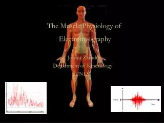
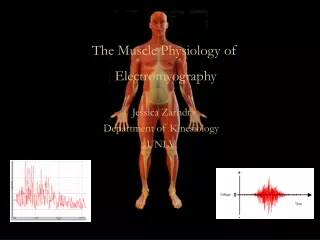
Electromyography Fundamentals Gregory S. Rash, EdD Electromyography (EMG) is the study of muscle function through analysis of the electrical signals emanated during muscular contractions. Electromyography is often abused and misused by many clinicians and researchers. Many times even experienced electromyographers fail to provide enough information and detail on the protocols, recording equipment and procedures used to allow other researchers to consistently replicate their studies. Hopefully, this chapter will clarify some of these problems and give the reader a basis for being able to conduct electromyography studies as part of their on-going research. Electromyography is measuring the electrical signal associated with the activation of the muscle. This may be voluntary or involuntary muscle contraction. The EMG activity of voluntary muscle contractions is related to tension. The functional unit of the muscle contraction is a motor unit, which is comprised of a single alpha motor neuron and all the fibers it enervates. This muscle fiber contracts when the action potentials (impulse) of the motor nerve which supplies it reaches a depolarization threshold. The depolarization generates an electromagnetic field and the potential is measured as a voltage. The depolarization, which spreads along the membrane of the muscle, is a muscle action potential. The motor unit action potential is the spatio and temporal summation of the individual muscle action potentials for all the fibers of a single motor unit. Therefore, the EMG signal is the algebraic summation of the motor unit action potentials within the pick-up area of the electrode being used. The pick-up area of an electrode will almost always include more than one motor unit because muscle fibers of different motor units are intermingled throughout the entire muscle. Any portion of the muscle may contain fibers belonging to as many as 20-50 motor units. A single motor unit can have 3-2,000 muscle fibers. Muscles controlling fine movements have smaller numbers of muscle fibers per motor units (usually less than 10 fibers per motor unit) than muscles controlling large gross movements (100-1,000 fibers per motor unit). There is a hierarchy arrangement during a muscle contraction as motor units with fewer muscle fibers are typically recruited first, followed by the motor units with larger muscle fibers. The number of motor units per muscle is variable throughout the body. For the purpose of this chapter there are two main types of electromyography: clinical (sometimes called diagnostic EMG) and kinesiological. Diagnostic EMG, typically done by physiatrists and neurologists, are studies of the characteris- tics of the motor unit action potential for duration and amplitude. These are typically done to help diagnostic neuromuscu- lar pathology. They also evaluate the spontaneous discharges of relaxed muscles and are able to isolate single motor unit activity. Kinesiological EMG is the type most found in the literature regarding movement analysis. This type of EMG studies the relationship of muscular function to movement of the body segments and evaluates timing of muscle activity with regard to the movements. Additionally, many studies attempt to examine the strength and force production of the muscles themselves. There is a relationship of EMG to many biomechanical variables. With respect to isometric contractions, there is a positive relationship in the increase of tension within the muscle with regards to the amplitude of the EMG signal recorded. There is a lag time, however, as the EMG amplitude does not directly match the build-up of isometric tension. One must be careful when trying to estimate force production from the EMG signal, as there is questionable validity of the relationship of force to amplitude when many muscles are crossing the same joint, or when muscles cross multiple joints. When looking at muscle activity, with regards to concentric and eccentric contractions, one finds that eccentric contractions produce less muscle activity than concentric contraction when working against equal force. As the muscle fatigues, one sees a decreased tension despite constant or even larger amplitude of the muscle activity. There is a loss of the high-frequency component of the signal as one fatigues, which can be seen by a decrease in the median frequency of the muscle signal. During move- ment, there tends to be a relationship with EMG and velocity of the movement. There is an inverse relationship of strength production with concentric contractions and the speed of movement, while there is a positive relationship of strength production with eccentric contractions and the speed of movement. One can handle more of a load with eccentric contrac- tions at higher speed. For example: If a weight was very large and you lowered it to the ground in a fast, but controlled manner, you handled a large weight at a high speed via eccentric contractions. You would not be able to raise the weight (concentric contraction) at the speed you were able to lower it. The forced production by the fibers are not necessarily any greater, but you were able to handle a larger amount of weight and the EMG activity of the muscles handling that weight would be smaller. Thus, we have an inverse relationship for concentric contractions and positive relationship for eccentric contractions with respect to speed of movement. With regards to recording the EMG signal, the amplitude of the motor unit action potential depends on many factors which include: diameter of the muscle fiber, distance between active muscle fiber and the detection site (adipose tissue thickness), and filtering properties of the electrodes themselves. The objective is to obtain a signal free of noise (i.e., movement artifact, 60 Hz artifact, etc.). Therefore, the electrode type and amplifier characteristics play a crucial role in obtaining a noise-free signal.
For kinesiological EMG there are two main types of electrodes: surface and fine wire. The surface electrodes are also divided into two groups. The first is active electrodes, which have built-in amplifiers at the electrode site to improve the impedance (no gel is required for these and they decrease movement artifacts and increase the signal to noise ratio). The other is a passive electrode, which detect the EMG signal without a built-in amplifier, making it important to reduce all possible skin resistance as much as possible (requires conducting gels and extensive skin preparation). With passive electrodes, signal to noise ratio decreases and many movement artifacts are amplified along with the actual signal once amplification occurs. The advantages of surface electrodes are that there is minimal pain with application, they are more reproducible, they are easy to apply, and they are very good for movement applications. The disadvantages of surface electrodes are that they have a large pick-up area and therefore, have more potential for cross talk from adjacent muscles. Additionally, these electrodes can only be used for surface muscles. Fine wire electrodes require a needle for insertion into the belly of the muscle. The advantages of fine wire electrodes are an increased band width, a more specific pick-up area, ability to test deep muscles, isolation of specific muscle parts of large muscles, and ability to test small muscles which would be impossible to detect with a surface electrode due to cross-talk. The disadvantages are that the needle insertion causes discomfort, the uncomfortableness can increase the tightness or spasticity in the muscles, cramping sometimes occurs, the electrodes are less repeatable as it is very difficult to place the needle/fine wires in the same area of the muscle each time. Additionally, one should stimulate the fine wires to be able to determine their location, which increased the uncomfortableness of using this type of electrode. However, for certain muscles, fine wires are the only possibility for obtaining their information. Differences between the recording of surface and fine wire electrodes, in part, are related to the differences in the bandwidths. Fine wire electrodes have a higher frequency and can pick-up single motor unit activity as the fine wire electrode band width ranges from 2-1,000 Hz, whereas surface electrode band width ranges from 10-600 Hz. Whether using surface or fine wire electrodes, there are some electrode configurations that can also aide in decreasing unwanted noise. A monopolar arrangement is the easiest as it is a single electrode and a ground. However, this arrangement picks up more unwanted signals than any of the other potential configurations. Bipolar arrangements are widely used in movement analysis. In this arrangement, there are two active electrodes and a ground. The process is to look at what is common with the two active electrodes and determine that this is noise and throw it away, keeping what is different in the two electrodes as the signal of interest. This is termed a differentially amplified system and is less prone to interference from adjacent and deeper muscles. A third arrangement is that of a double differentiated system. This is a system that has three active electrodes and one ground, therefore, possessing the ability to have two pairs of bipolar signals which are then again differentially amplified. This gives a smaller pick-up area, therefore, even less noise than the bipolar electrode by itself. These electrode arrangements are unique to the amplified system purchased and much thought should be given when purchasing a system so that at minimum a bipolar system is acquired. There are many other amplifier characteristics which should be noted. The first of which is the signal to noise ratio. This is the ratio of the wanted signal to the unwanted signal and is a measure of the quality of the amplified signal. The higher the ratio, the greater the noise reduction. Electrodes with on-site pre-amps (miniaturized and at the site of the electrode) are some of the best at providing a very large signal to noise ratio. The gain of the amplifier is also important. This is the amount of amplification applied to the signal and it should be sufficient enough to have output amplitude at 1.0 volt. Another important characteristic of the amplifier is the bandwidth. This is simply the range of the collectable frequencies of the amplifier, and one wants this high enough to reject the low frequency movement artifacts and low enough to attenuate the signal as little as feasible. This means in general, one should be collecting in a range from 0 Hz to 600 Hz for surface electrodes and 0 Hz to 1,000 Hz for fine wire electrodes. Using the Nyquest Theorem, this means that one must sample at a minimum of 1,200 Hz for surface electrodes and 2,000 Hz for fine wire electrodes in order to assure capturing the entire signal. Once the signals have been recorded, then one could use a 10-15 Hz high-pass filter to eliminate the movement artifacts (some prefer to use an analog filter on the front end, but I prefer to filter movement artifacts after collection). One must make sure all applied filters have zero phase shifts. The measure of the ability of the differential amplifier to eliminate the common mode signal is termed the common mode rejection ratio. The higher the common mode rejection ratio, the better the cancellation of common signals (noise). A value of 10,000 (80dB) is desirable. The input and impedance of the system should be greater than 1012 ohms and have a low input bias current of the order of 50 pica-amps or less. A high input impedance allows for as much of the signal available for amplification to be amplified. Any signal input below the input bias current is not amplified. With these characteristics in mind, one should be able to purchase an amplifier that is sufficient for collecting electromyography signals. There is also the potential for error introduced by the analog to digital board chosen. Most boards are only 10-12 bit boards and if the system does not allow full use of the collected range, one introduces error. This means if your collec- tion is set-up for +/- 10 volts and you are collecting EMG, which is in the +/- 1 volt range after amplification, you are not optimizing your system and you will have quantization and sampling error. Therefore, one must be sure that the software and hardware arrangement purchased allows for optimization of the collected voltage range within the A-D range.
The electromyographer must have a very good understanding of the anatomy of the human body as electrode location and placement is very important. First of all, one must be sure to clean the skin in order to reduce any skin resistance. This simple task can reduce the resistance of the skin by 200%. For many clinical applications of EMG, the belly of the muscle is used as a site for placing the electrodes. However, to assure repeatability of finding the specific site the electrode was placed, the use of bony landmarks as a reference is a must. There are numerous books and publications describing the exact locations of placement of the electrodes for this purpose. Another widely accepted method of placing the electrodes or surface electrodes is to use the motor point. As with placing the electrodes over the belly of the muscle, there are numerous publications that give the general motor point locations as a starting location, then you can find the exact position by using the motor point finder. Another specific issue that must be addressed is the inter-electrode distance. As many electrodes have a constant inter-electrode distance, several have a variable inter-electrode distance and one must be sure that this distance is kept constant throughout all subjects and trials to assure that the electrodes are over the same muscle fibers. There are many sources of noise (any unwanted signal collected along side the wanted signal) and some of these sources are: electrostatic field (skin), electromagnetic fields (power lines), motion artifact due to loose electrodes at the skin interface or loose leads on the wires, involuntary reflex activity (clonus), and any other electrical devise that might be in the room when the studies are occurring. The majority of these artifacts can be removed from the system by a few simple means. Proper cleaning of the skin is one such measure. If site pre-amplified electrodes are not used, this becomes a more crucial task. Using bipolar differentially amplified or double differentially amplified systems also help dramatically in the removal of artifacts from the system. Attaching all loose electrode leads and making sure that there is some slack in these leads is important as well. If your system has the possibility to use the battery supply as opposed to line feed for the power source, this is a great advantage and should be utilized. Prior to beginning the collection of data, one should check that the electrodes is making proper contact and that there is no tension on the wires and that all of the wires are plugged into all connectors sufficiently. Once the electrodes are in position the subject should have manual muscle tests applied for the specific muscles being tested to make sure that the electrodes are picking up muscle activity appropriately. If certain electrodes seem to be working inappropriately, one can try switching the leads if possible with their system, or just switch- ing electrode channels to see if this particular electrode works in another channel. If the signal is still bad after switching channels, one can switch electrodes to see if the electrode itself is malfunctioning. One must remember that there is a degradation of the signal as the amount of adipose tissue over the muscle being examined increases. Therefore, it may be difficult to pick-up any usable signal when dealing with obese individuals when using surface electrodes. One disadvantage of using the newer computerized collection systems is that many do not afford one the ability to see a raw EMG signal in real time (like an oscilloscope). It is imperative that one somehow view the raw signal prior to any processing (except an analog anti-aliasing filter) as it is often difficult to differentiate between signal and noise in a raw EMG signal and usually impossible to differentiate if any processing has been done to the EMG signal. Once the investiga- tor looks at the raw signal, they need to determine if there is any filtering which needs to be done. The novice electromyo- grapher may have trouble determining problems in the raw EMG signal. However, there are several items that can be looked at to help in this determination. Wavering base line is seen many times with low frequency movement artifacts. Additionally, large spikes can be indicative of abrupt movements of the electrode as well. Other things to look for are common signals across all channels and an underlying 60 Hz signal superimposed on the signal. If the signal does not look clean, the investigator may want to filter the data (some investigators say to always filter the data). There are three main types of filters applied to EMG data: high-pass, low-pass, and notch filters. There are many types of filters that can be applied such as: Butterworth, Chebyshev, etc. In this investigator?s lab, it is routine practice for us to use a fourth-order Butterworth high-pass digital filter with a 10-15 Hz cut-off, depending on the activity being analyzed (10 Hz for walking and 15 Hz for rapid movements) to remove movement artifacts. On the other end of the spectrum, we use an analog low- pass filter with a cut-off of 600 Hz for surface EMG and 1,000 Hz for fine wire EMG as an anti-aliasing filter. If it was determined that 60 Hz signals were superimpose within the signals, we would use a notch filter which would remove all signals within a 55-65 Hz range. Now that we have a clean EMG signal, we can begin to look at the signal to gain information about the muscles. The primary information to be gained is on and off information. In most movement analysis situations, only the raw EMG is used. No processing other than that which is used for cleaning up the raw signal (high and low-pass filters) is used. However, there are many common forms of processing that are done with EMG signals. The most common are: half-wave rectification (deletion of all negative aspects of the signal), full-wave rectification (absolute value of the entire signal), linear envelope (low-pass filtering of the full-wave rectified signal), root mean square (basically square the signal, take the mean of a timed determinant window about 100-200 ms, then take the square root), integrated EMG (area under the rectified curve can be determined for the entire activity or for pre-set time or amplitude values), and frequency analysis (typically determined via fast Fourier analysis and looking at the power density spectrum). Depending on your application, each of these processing techniques may have merit but each have disadvantages as well, since with any processing done to the data, information is lost.
For comparisons of EMG data from task to task or person to person, data needs to be presented in a common format. Thus, several means of normalization of the signal have been developed for both the time and amplitude domains. Probably the two most widely used time-base normalization techniques are to either normalize to a task/cycle or to phases within the task/cycle. As an example lets assume we want to look at the EMG of the back muscles with an individual who continually lifts items from the floor and places it in a bin. We can define a cycle as being from the initial movement of the object off the floor until the initial movement of the object off the floor for the successive lift. One would then just simply divide the time-base by the total amount of time it took to perform the task and then all movements would be with respect to the percent of the cycle. This works well for many cyclic tasks, but has disadvantages if the task contains more than one phase. Dividing up the time-base to the percent of a phase works well for task with multiple phases. Using the same lifting task, lets now define the lifting phase as being from the point that the object begins to move from the floor until the subject obtains a fully erect standing position. The second phase would then be from the point at which the subject reached the standing position until the item is placed in the bin and a third phase would begin at the point when the object was placed in the bin until the subject is back in position to lift another object. Each one of these phases is handled as a separate event. Thus, the time it took to lift from the floor to the standing position would be used as the divisor to make a percent phase for the lifting phase, the time it took from the point when the body reached an erect standing position until the item was in the bin would be used as the divisor for the second phase, and so on for the third phase. This type of time-based standardiza- tion is very useful when the task has clear phases that can be determined. For the sake of this example, lets say that the maximum EMG activity occurred just prior to setting the item down in the bin. It is much more meaningful to be able to say that the maximum amount of the EMG was found at 95% of the second phase than to say the maximum EMG was found at 55% of the task. From this point you would have to go back and figure out what movement was going on at 55% of the task. Additionally, the intra and inter subject variability of setting the object in the bin at the same point in a multiphase cycle is typically large. For this reason, our lab prefers to use percents of phases when possible. Many times the amplitude of the signal is normalized as well. Probably the most widely used is to standardize to the maximum voluntary isometric contraction (MVIC) for the specific muscle being used. Based upon published references for manual muscle testing, the examiner then applies a force to the body part in sufficient magnitude that the subject is unable to maintain a static position while exerting against the examiner with a maximum muscle contraction. It is debat- able if one can really ever obtain a true MVIC. Therefore, several other techniques have been devised. One of those is to use the maximum level of the signal across the entire task. In the lifting task previously described this would mean to take the maximum EMG level from each specific muscle during the entire task then normalize to this value. Many people prefer to use several peaks (4-5) and average these as the maximum so as to avoid the potential of using an erroneous high-spike as the maximum value. Another means of normalization is to use the mean level of the signal across the entire task. However, this is much less sensitive to any rapid peaks that were obtained during the task and would heavily skew the data if the majority of the signal contained times when the muscle was not active. A problem that exists when using the maxi- mum or mean level across the entire task is that the EMG signal will vary based upon the velocity of the joints during the contractions. Therefore, unless one standardizes the velocity of the task, this method may not allow for comparisons across tasks. Another technique very similar to the MVIC is to use a know level of force (e.g., Divide by the amplitude of the EMG when lifting 20 lbs. at the specific velocity that the task will be performed). Another variation of this is to use the amplitude of the EMG signal when exerting a known force against an immovable object, therefore, eliminating velocity from the equation. All of these methods have positive and negative attributes and they are means of trying to compare amplitudes between muscles and individuals. Additionally, if the subjects being examined have any pathological conditions that involve the muscles you are testing it will be virtually impossible to get a true MVIC and questionable whether the other normalization techniques are of any value as well. Regardless of the normalization technique used, whether it is time-based and/or amplitude based, one must remember that absolute information will be lost. Now that we have cleaned up the data and completed any normalization that we may want to do, it is time to look at the signal and try to interpret its meaning. First of all, one must understand that there is a large variability of the EMG signal itself. Whether this is task-to-task variability within the same person or person-to-person variability within the same task, many combinations of muscle activity can produce the same movements because of the redundancy present in the neuromuscular system. EMG can be variable from task to task because of this normal redundancy, velocity or cadence changes, or slightly different movement patterns even though under observation they look the same. A normal range of EMG phasing will exist for a task but one must be very cautious of trying to define discreet points in the tasks where these patterns begin and end. This must be kept in mind when interpreting the EMG signals. Other factors enter into the equation with interpreting the EMG of individuals with pathological conditions that influence the task-to-task variability. The changes in velocity or cadence, the onset of fatigue, and the presence of pain can all effect the EMG patterns. Another factor, which makes interpretation of the signal difficult, is cross talk. Cross talk is interference of the EMG signals from adjacent muscles or deeper muscles that are within the pick-up area of the electrode. There are no fixed solutions available at this point and the size of the patient and size of the electrode lead does play a major role in the ability to decrease or increase cross talk. For example, if your system has electrodes with fixed active electrode distances which are large and you
are working with a pediatric population you can be assured that your data will have large amounts of muscle information from adjacent and underlying muscles that is not wanted with your data. Many examiners utilize fine wire electrodes in order to try to remedy this problem. Now that we spent much time filtering and normalizing our data, it is time to discuss what the EMG signal can actually tell us. The muscle on and off timing patterns and relative increases and decreases in muscle activity are the two main parameters gained from the electromyography data. EMG data cannot tell us how strong the muscle is, if one muscle is stronger than another muscle, if the contraction is a concentric or eccentric contraction, or if the activity is under volun- tary control by the individual. The strength of the muscle or determining one muscle to be stronger than another is one of the main areas that researchers want to use EMG data for. The normalizing to the MVIC, the average, or max during the cycle are all attempts to allow us to be able to compare from muscle to muscle within the same person and from muscle to muscle between individuals. This is routinely done but one must be cautious of the results due to the problems inherent with the collection techniques and variability among muscles, individuals, and tasks. Besides using EMG for determining the EMG patterns (times of activation and times of rest) many researchers use electromyography for evaluating the changes in the signals as the muscles fatigue. All of these are valuable uses of electromyography in occupational biomechanics. Some specifics for use of surface and fine wire electrodes I. Surface EMG A. Skin Preparation 1. 2. Alcohol removal of dirt, oil, and dead skin. Shave excess hair if necessary. (Under ideal conditions this should always be done. However, it is not feasible in many cases.) If the skin is dry, some electrode gel rubbed into the skin can help. If the person is going to be sweating, spray an antiperspirant on the skin after cleaning with alcohol. B. Placement of Electrodes 1. There are specific references for different ways to measure for placement. (Norris, Johnson, Perotto) 2. General guidelines for large muscle groups: a) Best if over the largest mass of the muscle and align electrodes with muscle fibers b) Use motor point and motor point finder to locate (general location charts are available) C. Cross Talk 1. Not a real problem with large muscle groups. 2. Can sometimes be avoided my adjusting the electrode size, inter-electrode distance (if an option on your brand of electrode), or by use of fine wires. D. Application 1. Skin placement. 2. Avoid movement of electrodes by using straps or tape to firmly secure electrode in place. 3. Avoid bending of leads, place leads pointing in the direction that you want the wire to continue in. (e.g., For electrodes placed on an extremity, have the lead pointing towards the proximal end of the extremity so that the wire will not have to be bent in order to go in the proximal direction.) 4. Avoid any stress on the wires by making sure that the wires are loose underneath the tape or wrap that is holding them in place. Be sure to check when the wires cross the joint that once the joint is fully extended the wires are not drawn taunt. 5. Avoid placing electrodes over scars. 3. 4.
E. Testing 1. Do manual muscle tests to assure that you are getting a signal and that you are over the intended muscle. Do trial session to check signal and to get subject used to the setup and how instru- mented. 2. II. Fine Wire EMG A. Indications For small muscles. For deep muscles not accessible by surface electrodes. To isolate specific muscles from a muscle group or adjacent muscles. B. Preparation 1. Skin same as with surface electrodes. 2. Electrode: fine wires made as described by Basmajian and Stecko (wires typically connect to either the site pre-amplified electrode or fine wire connectors and some type of ground is used. 3. Can use topical agents: ethyl chloride, floromethane or EMLA patch or cream if desired (EMLA is a controlled substance in many countries). 4. Assistant: needed to help in preparation, stabilize patient?s extremity, or distract if needed. Having subject blow out forcefully as the needle is inserted works well. 5. It is usually easier to have the person in a laying position for insertion of the fine wire electrodes. 6. Inserter: needless to say, washing of hands and universal precautions are in order. C. Placement 1. Use of a cross sectional anatomy book or EMG guide to locate insertion point and the direction of application is advised. I prefer Anatomical Guide for Eelectromyography: The limbs and Trunk. 3rd ed. By Aldo Perotto, MD. Charles C. Thomas publisher. Springfield, Illinois. 2. Can check placement of the fine wires with electrical stimulation or my manual muscle testing if adjacent muscles would not be activated by the same movement needed for testing the selected muscle. 3. Can use fine sandpaper on the wire ends to improve the quality of signal. (Only the end which is to be attached to the electrode, as the other end must be sterile.) 4. After securing the wire to the electrode, tape the wire in place to the skin with small loop of wire to allow for movement. 5. It is a good idea to re-check the placement of the wires via electrical stim or manual muscle testing if questions arise during the collection process. D. Removal of the Wire 1. To remove the wires, gently pull the wires out and check the ends of the wire to assure that no wire broke off inside the body. 2. Special Sharps canisters are required for disposal of the needles. For disposal of the wire and gloves, you should check with your infection control or OSHA office to deter- mine what needs to be done at your facility. At our facility, unless the gloves and wires have dripping blood, which could easily get on some one, they can be disposed of in a standard trash can. If the blood could drip off, therefore being a biohazard, then a biohazard container must be used. E. Processing of the Fine Wire Electrodes 1. 2. 3. Easiest means of obtaining fine wire electrodes is directly from a vendor. We have used Nicolet Instru- ment Corporation [USA phone number (608) 271-3333] for purchasing fine wire electrodes. These electrodes come in packs of 10 (using 27-gage x 33mm needles) and can come in single or paired- hooked wires. One disadvantage to purchasing these needles already prepared is the limited number of size choices of needles. For example, in many individuals these needles are not long enough to reach the deep muscle being studied nor are the wires long enough once inserted to reach the electrode. In this case you can make your own electrodes as described by Basmajian and Stecko (1961) and then having them sterilized at your local hospital facility.
F. Data Collection for Surface and Fine Wire Electrodes 1. It is preferred to do no processing on the original data during collection (except an analog anti-aliasing filter) as it is difficult or impossible to know if noise has corrupted your data. 2. Collect surface EMG at a minimum of 1,200 Hz. 3. Collect fine wire EMG at a minimum of 2,000 Hz. 4. A high-pass filter with a cut-off of 10-15 Hz works well for removing movement artifact. 5. A front end analog low-pass filter at 600 Hz for surface EMG and 1,200 Hz for fine wire EMG works well as an anti-aliasing filter. 6. It is common to normalize the time-base to either a percent of the task involved or to percents of individual phases within the overall task. 7. There are several means of normalizing the amplitude of the signal: a) Percent MVIC b) Maximum level of signal across the task c) Mean level of signal across the task d) A known level of force 8. Common types of processing are: a) Half-wave rectification b) Full-wave rectification c) Linear envelope (a.k.a., mean absolute value or mean rectified value) d) Integrated EMG e) Frequency content analysis G. Additional Comments 1. When using EMG for research purposes: a) Care should be taken to use the appropriate units when reporting EMG data b) When referring to the amplifier gain, the units should be in a ratio or dB c) The input impedance should be expressed in ohms d) The common mode rejection ratio should be as a ratio or in dB e) When referring to filter band widths cut-off, the units should be in Hz f) EMG, when a raw, average or rectified signal, should be referred to in millivolts g) If the EMG has been integrated, then it should be expressed in terms of millivolt seconds with the specific period of analysis. If the integrated EMG was time reset or voltage reset, then the specific time or voltage should be indicated. Otherwise, individuals would not be able to reproduce the study that you have conducted. With this overview of electromyography use in movement analysis, the reader should have a good idea of what the general process entails. By no means does this chapter give the investigator all the knowledge needed with becoming a proficient electromyographer. However, it gives a good overview and when augmented with other readings and material the reader should be able to utilize electromyography as a tool in their research.
REFERENCES Basmajian JV, et al. Computers in Electromyography. Butterworths, 1975. Basmajian JV, Deluca CJ. Muscles Alive: Their functions revealed by electromyography 5th ed. Will- iams and Wilkins, Baltimore, 1986. Basmajian JV, Stecko GA. ?A new bipolar indwelling electrode for electromyography.? J Applied Physiology, 17: 849, 1961. Eberstein A, Beattie B. ?Simultaneious measurement of muscle conduction, velocity, and EMG power spectrum changes during fatigue.? Muscle & Nerve, 8: 768-773, 1985. Ganong WF. Review of Medical Physiology 10th ed. Lange, Los Altos, 1981. Goldgood J. Anatomical Correlates fo Clinical Electromyography 2nd ed. Williams and Wilkins, Balti- more, 1984. Harris GF, Wertsch JJ. ?Procedures for gait analysis.? Arch Physical Medicine & Rehab, 75:216-225, 1994. Henneman E, Somjen G, Carpenter DO. ?Excitability and inhabitability of motorneurons of different sizes.? J Neurophysiology, 28: 599-620, 1965. Johnson EW. Practical Electromyography 2nd ed. Williams and Wilkins, Baltimore, 1988. Kendall FP, McCreary EK. Muscles, Testing and Function 3rd ed. Williams and Wilkins, 1983. Kimura J. Electrodiagnosis in disease of Nerve and Muscle, Principles and Practice 2nd ed. F Davis Co., Philadelphia, 1989. Koh TJ, Grabiner MD. ?Evaluation of methods to minimize crosstalk in surface EMG.? J Biomechan- ics, 26 Suppl: 151-157, 1993. Kwatney E, et al. ?An application of signal processing techniques to the study of myoelectric signals.? IEEE Transactions on BioMedical Engineering, Vol. BME-17, No. 4: 303-312, Oct 1970. Muro M, et al. ?Surface EMG power spectral analysis of neuromuscular disorders during isometric and isotonic contractions.? American J Physical Medicine, 61(5): 244-253, 1982. Nilsson J, Panizza M, Hallet M. ?Principles of digital sampling of a physiologic signal.? EEG and Clinical Neurophysiology, 89: 349-58, 1993. Norris FH. The EMG: A Guide and Atlas for Practical EMG. Gruve and Stratton, New York, 1963. Seigler S, et al. ?Effect of myoelectric signal processing on the relationship between muscle force and processed EMG.? American J Physical Medicine, 64(3): 130-149, 1985.
Shavi R. ?Electromyographic patterns in adult locomotion: A comprehensive review.? J Rehab Res & Dev, 22(3): 85-98, July 1985. Shavi R, Green N. ?Ensemble averaging of locomotor electromyographic patterns using interpolation.? Med & Biol Eng & Comput, 21: 573-578, 1983. Solomonow M, Baten C, Smit J, Baratta R, Hermens H, D?Ambrosia R. ?EMG power spectra frequen- cies associated with motor unit recruitment strategies.? J Applied Physiology, 68: 1177-1185, 1990b. Solomonow M, Baratta R, Bernardi M, Zhou B, Lu Y, Acierno S. ?Surface and wire EMG crosstalk in neighboring muscles.? J Electromyography & Kinesiology, 4: 131-142, 1994. Winter DA, Fuglevand AJ, Archer SE. ?Crosstalk in surface EMG: theoretical and practical estimates.? J Electromyography & Kinesiology, 4(1): 15-26, 1994. Winter DA. The Biomechanics and Motor Control of Human Gait. University of Waterloo Press, Waterloo, Ontario, 1988. Winter DA, Rau G, Kadefors R, Broman H, Deluca CJ. Units, Terms, and Standards in the Reporting of EMG Research: A Report by the AdHoc Committee of the International Society of Electrophysiology and Kinesiology. Aug 1980.