Download
1 / 17
170 likes | 197 Vues
SuperB IFR: outline of the IFR DAQ electronics. Summary prototype detector and electronics for a proof of principle updated IFR detector data bandwidth and event size estimates. outline of the IFR DAQ electronics: prototype detector and electronics for a proof of principle.

E N D
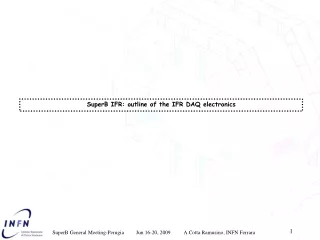
SuperB IFR: outline of the IFR DAQ electronics SuperB General Meeting-Perugia Jun 16-20, 2009 A.Cotta Ramusino, INFN Ferrara
Summary • prototype detector and electronics for a proof of principle • updated IFR detector data bandwidth and event size estimates SuperB General Meeting-Perugia Jun 16-20, 2009 A.Cotta Ramusino, INFN Ferrara
outline of the IFR DAQ electronics: prototype detector and electronics for a proof of principle • SuperB IFR prototype: • 5 layers of x-y scintillators, 1 cm thick, read in binary mode • 3 layers of scintillators 2 cm thick, read in timing mode to LST_FE to TDC A.C.R. 2009-02-11 • SuperB-IFR prototype readout electronics (baseline): • “IFR_ABC”: sensor amplification, bias-conditioning, discrimination • “LST-FE”: front end card used in BaBar IFR equipped with PECL receiver daughter cards. It samples status of inputs @ 80MHz and stores it, pending the trigger request • “IFR_FE_BiRO”: collects data from LST-FE cards upon trigger request and sends it to DAQ PC (via GbE) • “IFR_FE_TDC”: a multi-hit TDC design based on commercially available TDC chips with trigger interface and GbE output link to the DAQ PC • “IFR_TLU”: a module (Trigger Logic Unit) to generate a fixed latency trigger based on primitives from the IFR prototype itself or from external sources SuperB General Meeting-Perugia Jun 16-20, 2009 A.Cotta Ramusino, INFN Ferrara
Threshold DAC Bias DAC outline of the IFR DAQ electronics: prototype detector and electronics for a proof of principle • “IFR_ABC” card features: • ampli: two stage w/discrete components: either 2 xTHS4303 (2.6$ea) or BGA2748(0.42$ea) + BGA2716(0.33$ea) • discri: ADCMP562BRQ (dual, 2.7$ea) • For the SuperB IFR prototype it is foreseen to use two comparators at different thresholds (2.5 pe and 1.5 pe for instance) for each sensor • DAC: MAX5592 (10bit, octal, 5.24$ea) • CPLD: ALTERA EPM1270GT144C5N (22$ ea) • signal connector compatible with BaBar IFR signal cables (re-usable): KEL 8831E-034-170LD (3€ea for the PCB-mount+ 6.5€ea for the cable mount) Programmable bias voltage 10 x 10 x 10 x 2 x KEL connector 20 x 10 x comparator w/ fixed pulse width w/ diff P-ECL outputs ampli SiPM 10 x 20 x It was recently decided to locate the elements in the grey box INSIDE the IFR iron (because it was finally rejected the idea of carrying scintillation light out of the iron on clear optical fiber due to excessive attenuation) the front end will have to be power-optimized and characterized for radiation tolerance Power and serial interface connector A.C.R. 2009-06-16 MAX-II CPLD Outline of the “IFR_ABC” card (Amplifier, Bias, Comparator) SuperB General Meeting-Perugia Jun 16-20, 2009 A.Cotta Ramusino, INFN Ferrara
outline of the IFR DAQ electronics: prototype detector and electronics for a proof of principle “IFR_ABC” card “core” built for radiation damage tests at FNG facility: “MMIC-Type”: based on the MMIC amplifiers BGA2748/BGA2716 amplifier Dual comparator w/ digital pulse shaping SuperB General Meeting-Perugia Jun 16-20, 2009 A.Cotta Ramusino, INFN Ferrara
outline of the IFR DAQ electronics: prototype detector and electronics for a proof of principle “IFR_ABC” card “core” waveforms: “MMIC-type” waveform C1: output of ampli stage with (attenuated by a factor 2) C4: differential output of one discriminator/shaper with a threshold of -180mV Single p.e. signal “MMIC-type” waveform C1: output of ampli stage with (attenuated by a factor 2) C4: differential output of one discriminator/shaper with a threshold of -150mV SuperB General Meeting-Perugia Jun 16-20, 2009 A.Cotta Ramusino, INFN Ferrara
outline of the IFR DAQ electronics: prototype detector and electronics for a proof of principle “IFR_ABC controller card” (R.Malaguti): it features, among other things, the circuitry to individually tune the bias voltage to the sensors It was recently decided to locate the front end elements INSIDE the IFR iron (because it was finally rejected the idea of carrying scintillation light out of the iron on clear optical fiber due to excessive attenuation) the individual bias regulator will have to be characterized for radiation tolerance SuperB General Meeting-Perugia Jun 16-20, 2009 A.Cotta Ramusino, INFN Ferrara
outline of the IFR DAQ electronics: prototype detector and electronics for a proof of principle Multihit TDC candidates: • reference clock frequency: 40MHz • no “trigger matching” function • reference clock frequency: 40MHz • “trigger matching” function: On-chip trigger matching could be exploited with great advantage when the L1 trigger is at fixed latency w.r.t. the event, as proposed by D.Breton (LAL), U.Marconi (INFN) in: “Proposal for the Electronics Trigger and DAQ architecture of SuperB”. But… SuperB General Meeting-Perugia Jun 16-20, 2009 A.Cotta Ramusino, INFN Ferrara
outline of the IFR DAQ electronics: prototype detector and electronics for a proof of principle Multihit TDC candidates: … continuing: the L1 trigger handling outlined in« Modelisation of SuperB Front-End Electronics » (Christophe Beigbeder, Dominique Breton, Jihane Maalmi) cannot be performed by the HP-TDCs on chip trigger matching function ALL DATA MUST BE TRANSFERRED FROM THE TDC TO AN OFF-CHIP DATA STORAGE MANAGED BY AN FPGA WHICH COULD IMPLEMENT THE MODELS SUGGESTED IN THE PAPER: THE HP-TDC LOOSES ITS ADVANTAGE OVER ACAM’s TDC-GPX, commercially available and of simpler usage SuperB General Meeting-Perugia Jun 16-20, 2009 A.Cotta Ramusino, INFN Ferrara
outline of the IFR DAQ electronics: prototype detector and electronics for a proof of principle “IFR_FE_TDC_DC” • “IFR_FE_TDC” card features: • motherboard: it is based on an ALTERA development board for the Cyclone III FPGA (DK-DEV-3C120N, cost 1000 €). The Cyclone III FPGA on board continuously collects data from the “IFR_FE_TDC_DC” daughter card and stores it in a circular buffer pending a trigger request. Data requested by a trigger is sent over the on-board GbE link. • daughter card ( “IFR_FE_TDC_DC” ): it features commercially available TDCs (8 x ACAM TDC-GPX as a baseline) to handle at least 64 channels per board. An on-board FPGA configures the TDC chips, provides the primary buffers into which dat is stored pending the trigger request and performs transfer of “trigger matched data” through a FIFO-buffered output port towards the motherboard. TDC chips and “Glue” FPGA 4 x KEL connectors pECL to TTL translators Trigger Interface TRIGGER PORT HSMC HSMC A.C.R. 2009-02-11 It is assumed that the TDC could be located far enough from the IFR iron to be in a low radiation environment SEU mitigation resources provided by the CycloneIII FPGA should suffice Outline of the “IFR_FE_TDC” card SuperB General Meeting-Perugia Jun 16-20, 2009 A.Cotta Ramusino, INFN Ferrara
outline of the IFR DAQ electronics: data bandwidth estimates WITH TIMING READOUT FOR BARREL (updated) • SuperB-IFR numerology: • Barrel: N_Barrel = 3600 scintillator bars • ( quoting G. Cibinetto ) • Assuming: • readout in TIMING mode with N_th( =2) thresholds: • both the high threshold (2.5 p.e. for instance) and the low threshold (1.5 p.e. for instance) crossing times are acquired by the F.E., the second threshold crossing validating the first for better noise rejection. • -> each scintillator is readout at both ends • -> total number of TDC channels: N_TDC_ch N_TDC_ch= (N_Barrel) * 2 * N_th = 14.400 N_TDC_board= N_TDC_ch/ 64 = 225 W.Sands., Princeton Univ., 2003 Hopefully the tests on the prototype will show that it will be possible to keep: N_th = 1 but in the meantime it is better to consider the worst option !!! Multihit TDC ASICs currently available assume a reference clock of 40MHz meanwhile the latest document edited by D.Breton and U. Marconi assumes a 56.25MHz clock: it is an issue !!! SuperB General Meeting-Perugia Jun 16-20, 2009 A.Cotta Ramusino, INFN Ferrara
outline of the IFR DAQ electronics: data bandwidth estimates WITH TIMING READOUT FOR BARREL (updated) SuperB-IFR numerology: “Physics” rate : 500kHz/channel, in the hottest region, arising from: - particle rate : O(100Hz) / cm2 (including background) - dimensions of a detector element : < 400cm x 4cm (thickness 20mm) (quoting R.Calabrese, W.Baldini, G.Cibinetto) “Dark count” rate : for a 1mm2 SiPM by FBK: (quoting R.Malaguti, L.Milano test results in Ferrara) @ 0.5pe threshold - @ 25˚C, 34.4V: ≈ 360kHz - @ 5˚C, 33.8V: ≈ 128kHz • @ 2.5pe threshold • @ 25˚C, 35V: ≈ 20kHz • - @ 5˚C, 34V: ≈ 6.3kHz !!! The “dark count” rate scales with the sensor’s area and we don’t know yet which would be the final area of the sensor of choice ( a 4mm2 is also being considered ) !!! We need to have, on each processing channel, one comparator with a low threshold (0.5pe? 1.5pe? Only prototype test will tell) it’s TDC input will see the highest rate. Let’s consider a “Hit” rate of: Hit_rate= physics_rate + dark count_rate ≤ 1MHz per TDC input!!! it is compatible with the TDC-GPX maximum sustained input rate SuperB General Meeting-Perugia Jun 16-20, 2009 A.Cotta Ramusino, INFN Ferrara
outline of the IFR DAQ electronics: data bandwidth estimates WITH TIMING READOUT FOR BARREL (updated) if we do L1 trigger matching on board • Assumptions on L1 trigger rate and window: • L1 trigger at fixed latency with respect to the event: • L1 trigger rate : 150KHz (*) • L1 trigger window : 1us (*) • (*) (quoting “Electronics, trigger and DAQ for SuperB.”, D. Breton, U.Marconi, Feb. 11 2009) • Assuming that: • trigger matched “Hits” are packed into FRAMES • Each FRAME contains: • Header = Board ID + Frame ID (allows to reconstruct ABSOLUTE timing for hit records) : 12 Byte • Channel ID + hit timing information RELATIVE to beginning of frame : 4 Byte per Hit • Trailer = WordCount + error code : 4 Byte • On each TDChalf of the channels has a 1MHz input rate and half has a 500KHz input rate • we can expect, for a 64 channel TDC card, an average frame size of: <Frame size> = 12 + (1 hit * 32 + 0.5 hit * 32) * 4 + 4 ≈ 12 + 48 * 4 + 4 ≈ 0.21kB • Each 64 channel TDC card would produce a “TRIGGER MATCHED” sustained stream of (on average) : • <Bandwidth per 64ch TDC> = 150kHz * 0.21kB ≈ 32MB/s • (it would be less if we could implement: • D.Breton’s scheme to handle the “overlap” of trigger requested data • the BhaBha veto) A.C.R. 2009-02-13 Average event size for the whole Barrel read in timing mode: <Event size Barrel> = 0.21kB * 225 ≈ 47kB SuperB General Meeting-Perugia Jun 16-20, 2009 A.Cotta Ramusino, INFN Ferrara
outline of the IFR DAQ electronics: data bandwidth estimates WITH BINARY READOUT FOR ENDCAP (updated) • SuperB-IFR numerology: • EndCaps: N_EndCap = 2400 + 2400 scintillator bars • ( quoting G. Cibinetto ) • Assuming: • the number of (thin) scintillators doubles • (for X-Y readout; it’s a coarse estimate) • readout in BINARY mode with single threshold: • each scintillator is readout from N_sides(=2) ends • -> total number of BiRO channels: N_BiRO_ch N_BiRO_ch= (N_EndCap) * 2 * N_sides= 19.200 N_BiRO_Board= N_BiRO_ch/ 128 ≈ 150 W.Sands., Princeton Univ., 2003 It is possible that construction / dead space constraints will result in : N_sides= 1 at least for part of the scintillators but let’s now consider the full number SuperB General Meeting-Perugia Jun 16-20, 2009 A.Cotta Ramusino, INFN Ferrara
outline of the IFR DAQ electronics: data bandwidth estimates WITH BINARY READOUT FOR ENDCAP (updated) SuperB-IFR numerology: “Physics” rate : 500kHz/channel, in the hottest region, arising from: - particle rate : O(100Hz) / cm2 (including background) - dimensions of a detector element : < 400cm x 4cm (thickness 20mm) (quoting R.Calabrese, W.Baldini, G.Cibinetto) “Dark count” rate : for a 1mm2 SiPM by FBK: (quoting R.Malaguti, L.Milano test results in Ferrara) @ 0.5pe threshold - @ 25˚C, 34.4V: ≈ 360kHz - @ 5˚C, 33.8V: ≈ 128kHz • @ 2.5pe threshold • @ 25˚C, 35V: ≈ 20kHz • - @ 5˚C, 34V: ≈ 6.3kHz !!! The “dark count” rate scales with the sensor’s area and we don’t know yet which would be the final area of the sensor of choice ( a 4mm2 is also being considered ) !!! We need to have, on each processing channel, just one comparator with a 2.5pe threshold The dark count rate @ 2.5pe threshold is just a fraction of the physics rate Let’s consider a “Hit” rate of: Hit_rate= physics_rate + dark count_rate≈600kHz per BiRO input SuperB General Meeting-Perugia Jun 16-20, 2009 A.Cotta Ramusino, INFN Ferrara
outline of the IFR DAQ electronics: data bandwidth estimates WITH BINARY READOUT FOR ENDCAP (updated) if we do L1 trigger matching on board • Assumptions on L1 trigger rate and window: • L1 trigger at fixed latency with respect to the event: • L1 trigger rate : 150KHz (*) • L1 trigger window : 1us (*) • (*) (quoting “Electronics, trigger and DAQ for SuperB.”, D. Breton, U.Marconi, Feb. 11 2009) • Assuming that: • input channels are sampled at 100MHz and the FPGA evaluates, in response to a trigger, the addresses of active channels within the trigger acceptance window and the sample ID within the window • Each FRAME contains: • Header = Board ID + Frame ID (allows to reconstruct ABSOLUTE timing for hit records) : 12 Byte • Channel ID + Sample ID for which the “Hit” was found : 2 Byte per Hit • Trailer = WordCount + error code : 4 Byte • We can expect, for a 128 channel BiRO Front End Card, an average frame size of: <Frame size> = 12 + <0.6> hit * 128 * 2 + 4 ≈ 12 + 77 * 2 + 4 ≈ 0.17kB • Each 128 channel Bi-RO card would produce a “TRIGGER MATCHED” sustained stream of (on average) : • <Bandwidth per 64ch TDC> = 150kHz * 0.17kB ≈ 26MB/s • (it would be less if we could implement: • D.Breton’s scheme to handle the “overlap” of trigger requested data • the BhaBha veto) A.C.R. 2009-02-13 Average event size for the whole ENDCAP read in BINARY mode: <Event size ENDCAP> = 0.17kB * 150 ≈ 25.5kB SuperB General Meeting-Perugia Jun 16-20, 2009 A.Cotta Ramusino, INFN Ferrara
outline of the IFR DAQ electronics: data bandwidth estimates WITH BINARY READOUT FOR ENDCAP (updated) Summary BARREL readout in TIMING mode ENDCAP readout in BINARY mode number of BiRO_Board≈ 150 number of TDC_board≈ 225 Channel per board= 128 Channel per board= 64 Bandwidth per board (trigger matched): 26MB/s Bandwidth per board (trigger matched): 32MB/s Average event size for the whole Barrel read in timing mode: <Event size Barrel> = 0.21kB * 225 ≈ 47kB Average event size for the whole ENDCAP read in BINARY mode: <Event size ENDCAP> = 0.17kB * 150 ≈ 25.5kB SuperB General Meeting-Perugia Jun 16-20, 2009 A.Cotta Ramusino, INFN Ferrara