PLC Programming Examples: Output Instructions Condition (True/False) Evaluation
Understand output instruction conditions with multiple examples showing the evaluation process based on input conditions. Study XIC, XIO, OTE instructions, and timer operations in PLC programming.

PLC Programming Examples: Output Instructions Condition (True/False) Evaluation
E N D
Presentation Transcript
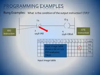
Programming Examples Rung Examples: What is the condition of the output instruction? (T/F)? O:3 I:1 OTE Instruction XIO Instruction 2 1746-IA8 4 1746-OB16 I:0 Input image table shows 0 bit in I:1/2 XIO evaluates TRUE. 0 I:1 I:4 Input image table et438b-10
Programming Examples Rung Examples: What is the condition of the output instruction? (T/F)? O:3 I:1 True TRUE 2 1746-IA8 4 1746-OB16 Rung is TRUE, so OTE is TRUE. Output image table O:2 1 O:3 O:5 et438b-10
Programming Examples Rung Examples: What is the condition of the output instruction? (T/F)? XIO Instruction I:2 I:3 O:1 OTE Instruction XIC Instruction 5 1746-IA8 0 1746-IA8 3 1746-OB8 Input image table Location I:2/5 = 1. XIC evaluates as TRUE.. 1 I:2 0 I:3 I:4 Location I:3/0 = 0. XIO instruction evaluates as TRUE. et438b-10
Programming Examples Rung Examples: What is the condition of the output instruction? (T/F)? I:2 I:3 O:1 True TRUE TRUE 5 1746-IA8 0 1746-IA8 3 1746-OB8 Output image table TRUE AND TRUE = TRUE Output image will have 1 at address O:1/3 O:0 1 O:1 O:5 et438b-10
Programming Examples Rung Examples: What is the condition of the output instruction? (T/F)? O:0 I:0 TRUE OR FALSE = TRUE so rung is TRUE, OTE is TRUE True FALSE 3 1746-IA8 5 1746-OB8 I:0 TRUE Output Image Table location O:0/5 = 1. This output will be energized 7 1746-IA8 Input image table Input image table shows I:0/0 = 1 and I:0/3 = 0 1 0 I:0 I:1 The first XIC instruction at input I:0/3 evaluates as a FALSE XIC at input I:0/7 evaluates as TRUE (bit =1) I:4 et438b-10
Programming Examples Rung Examples: What is the condition of the output instruction? (T/F)? FALSE OR FALSE = FALSE The rung evaluates FALSE O:4 I:1 FALSE FALSE The instruction OTE evaluates FALSE 0 1746-IA16 0 1746-OB16 I:0 FALSE In the output image file, O:4/0 = 0 and output will not be energized 2 1746-IA16 Input image table 1 I:0 0 I:1 At input I:1/0 =0, XIC evaluates FALSE At input I:0/2 = 1, XIO evaluates FALSE et438b-10
Toggling Bits in the Bit File The instructions XIC, XIO and OTE operate on bits in the B4 bit file also. Use these bits like control relays in electromechanical schemes. Not related to I/O points I:0/1=0 Rung Examples I:0 B3:2 B3:2/2=0 TRUE FALSE TRUE FALSE 2 I:0/1=1 1 B3:2/2 = bit number 2 in word 2 of the B3 file This will be toggled by the input I:0/1 B3:2/2=1 I:0 B3:1 Input at location I:0/2 toggles the bit B3:1/1 TRUE TRUE FALSE FALSE 2 1 The XIC instruction acts like a seal-in contact in electromechanical systems B3:1 TRUE 1 FALSE et438b-10
Timer Instructions Timer Type Enable Bit Timer on-delay (TON) Done Bit FALSE TRUE Time base selectable in some models Operation: when rung becomes TRUE, timer activates Preset time delay Timer stops when rung becomes FALSE Accumulated time since activation resets for Rung FALSE Addressable Bits DONE (DN) - bit set (1) when ACC=PRE ENABLE (EN) - bit set (1) when rung TRUE Timer Timing (TT) - bit set (1) when ACC<PRE and rung TRUE ACCUM = ACC, accumulated time value since activation PRESET = PRE, set time delay. depends on time base et438b-10
Timer Instructions Timer: off-delay (TOF) FALSE TRUE Operation Timer activates when rung conditions become FALSE (make a TRUE to FALSE transition Timing Timer operated as long as rung remains FALSE Accumulator reset when rung goes TRUE Preset and Accumulator are the same as in TON Addressable bits DONE (DN) - bit is reset (0) when ACC = PRE ENABLE (EN) - bit is set (1) when rung conditions TRUE Timer Timing (TT) - bit is set (1) when rung conditions FALSE and ACC < PRE et438b-10
15 14 13 0 EN TT DN INTERNAL USE ONLY 0 Preset Value (PRE) 1 Accumulated Value (ACC) 2 Timer Instruction Examples TRUE Timer T4:0 first timer in program I:0 FALSE Time base 0.01 sec, preset to 100 (1 sec) delay 2 Initial conditions I:0/2 = 0 Rung evaluates FALSE Bit status EN = 0 TT = 0 DN = 0 I:0/2 = 1 rung evaluates TRUE t= 0 sec Bit status EN = 1 TT =1 DN = 0 When PRE = ACC = 100 Bit status EN = 1 TT = 0 DN = 1 EN = 1 until I:0/2 = 0 1 1 0 0 0 et438b-10
15 14 13 0 EN TT DN INTERNAL USE ONLY 0 Preset Value (PRE) 1 Accumulated Value (ACC) 2 Off-Delay Timer Example TRUE Initial conditions: input bit instruction XIC B3:0/1 = 1 rung is TRUE . Timer is not activated B3:0 FALSE 1 B3:0/1 = 0 TRUE to FALSE transition timer starts Bit status EN = 0 TT = 1 ACC<PRE DN = 1 ACC<PRE Note: DN remains set until ACC = PRE When PRE = ACC = 100 (1 sec) Bit status EN = 0 TT = 0 ACC = PRE DN = 0 If rung goes TRUE ACC =0 EN = 1 DN = 1 TT = 0 0 1 1 0 0 et438b-10
Timer Example Example: Using a timer to turn on an output after a 3 second delay FALSE TRUE I:1 0 1 1 0 3 When input changes state I:1/3 = 1 Rung is TRUE t Timer bit status EN = 1 TT=1 DN = 0 FALSE O:0 T4:0 2 DN 0 Initial conditions: Input address I:1/3 = 0 Rung 1 evaluates FALSE Timer Bit status EN = 0 TT = 0 DN = 0 PRE = 300 Rung 2 T4:0/DN = 0 XIC instruction evaluates FALSE so O:0/0 = 0 et438b-10
Timer Example-Continued Rung 2 T4:0/DN = 0 rung FALSE O:0/0 = 0 Output is de-energized I:1 1 1 0 1 3 FALSE TRUE O:0 T4:0 On 2 DN 0 At t = 3 seconds Rung 1 I:1/3 = 1 PRE = ACC = 300 Timer bits EN = 1 TT = 0 DN =1 Rung 2: T4:0/DN = 1 XIC evaluates TRUE Rung is TRUE O:0/0 = 1 Output energized et438b-10
Counter Instructions Counters used to accumulate a count of events that cause FALSE to TRUE transitions on the input to the counter rung Count Up (CTU) and Count Down (CTD) Count up instruction Addressable Bits Counter up enable (CU) = bit is set (1) when the rung goes TRUE Counter Done (DN) = bit is set (1) when the preset and accumulated values are equal Counter accumulator values are retentive. The value is not cleared until a RES instruction is issued that addresses the counter et438b-10
Counter Instructions Count Down (CTD) Counter decrements the preset value by 1 each time the rung makes FALSE-TRUE transition When ACCUM < PRESET the DN = 1 Counter Done bit (CD) = set (1) when rung is TRUE Reset when the rung is FALSE Underflow and Overflow conditions Bit OV set (1) when ACC = 32,767 +1 BItUV set (1) when ACC = -32768-1 et438b-10
The Reset Instruction Reset (RES) - instruction used to reset timing and counting functions Reset - output instruction resets counters and retentive timers having the same address as the RES instruction Reset occurs when rung becomes TRUE I:1 Input I:1/6 actuates RES instruction that clears counter C5:0 ACCUM = 0 CU = 0 4 C5 I:1 6 0 et438b-10
Counter Addressing Example TRUE When I:1/5 = 1, rung 1 evaluates TRUE CTU increments I:1 1 C5:1/CU = 1 when rung 1 TRUE Turning on O:2/4 5 1746-IA8 TRUE +1 1 C5:1 O:2 C5:1/DN bit will be set when ACC = PRE = 100 setting O:2/5=1 2 1 CU 4 TRUE C5:1 O:2 3 1 DN 5 The overflow bit C5:1\OV = 1 when ACC = 32,767+1 Counter “wraps around” 32,767+1 = -32,768 C5:1 O:2 4 OV 6 et438b-10
Programming Ladder Logic in a PLC Ladder Logic is similar to PLC rungs but not Identical Logical continuity not equivalent to electrical continuity Programming Process Must divide system into field inputs, field outputs and internal (bit) devices Evaluate the function of the field contacts when assigning XIO and XIC instructions to field inputs et438b-10
Programming Ladder Logic in a PLC Example:Three wire motor starter control with overload protection relay on M1 is motor contactor coil, contact M1 is auxiliary contact mechanically linked to M1 Demonstrate operation et438b-10
Programming Ladder Logic in a PLC Defining Field Devices Field Inputs Field Output Start/Stop, M1 contact and OL contacts are all fieldinputs for PLC operation. Contacts located on external equipment. M1 coil is a field output. PLC must energize the motor contactor coil based on the state of the inputs et438b-10
Programming Ladder Logic in a PLC Step 1 – Defining I/O and Developing External Wiring Diagrams Define Address of I/O points and wire field devices to I/O points. Assume only slot 0 is populated with I/O points and all I/O 120 V ac Inputs STOP = I:0/0 START = I:0/1 OL = I:0/2 M1 = I:0/3 Output(s)M1 = O:0/0 Contacts need a source of 120 V ac to actuate the electronics of the I/O cards (120 V ac I/O) et438b-10
Programming Ladder Logic in a PLC Module External Wiring I:0/0 O:0/0 I:0/1 I:0/2 I:0/3 Output wiring Input wiring et438b-10
Programming Ladder Logic in a PLC Step 2 – Converting Ladder Diagram into PLC Program Having Field devices in the NC state does not automatically translate to XIC instruction (NC symbol) Rung instructions must evaluate to TRUE for OTE instruction to evaluate TRUE and energizing the external hardware Review logic of bit instructions Logic of XIC Logic of XIO Bit Result 1 FALSE 0 TRUE Bit Result 1 TRUE 0 FALSE et438b-10
O:0/0 I:0/1 I:0/0 I:0/2 I:0/3 Programming Ladder Logic in a PLC Step 2 – Converting Ladder Diagram into PLC Program Programming rung exactly like ladder diagram will not work XIO XIO M1 N.O. False OL N.C. Logic to implement START PB N.O. (START OR M1) AND STOP AND OL = M1 3 2 1 0 XIO evaluates as FALSE for STOP and OL contacts 0 1 0 1 Input Image Map ( bit status) STOP PB N.C. et438b-10
O:0/0 I:0/1 I:0/0 I:0/2 I:0/3 Programming Ladder Logic in a PLC Correct Rung Programming: Motor Control Example Start Input Image Map ( bit status) M1 Aux 1 0 1 0 1 3 1 2 0 For rung to be TRUE input statement must evaluate TRUE (START OR M1) AND STOP AND OL = M1 START = STOP = OL = 1 OR M1 = STOP = OL =1 Use XIC for Both OL and STOP et438b-10 Use XIC instruction TRUE = 1 FALSE = 0
M1 OL STOP START I:0/0 I:0/1 I:0/2 O:0/0 M1 I:0/3 Programming Ladder Logic in a PLC PLC rung for motor control: note all instructions are XIC TRUE TRUE TRUE XIC instructions all evaluate TRUE but M1 ((TRUE OR FALSE) AND TRUE) AND TRUE = M1 TRUE =M1 Output O:0/0 bit set Pressing START gives the following input image Start 0 1 1 1 M1 3 2 1 0 et438b-10
M1 OL STOP START I:0/0 I:0/1 I:0/2 O:0/0 M1 I:0/3 Programming Ladder Logic in a PLC Rung Logic After the Release of START Contact M1 changes state due to mechanical linkage to contactor coil so.... TRUE TRUE START momentary contact returns to open TRUE FALSE XIC instructions all evaluate TRUE but START input (START OR M1 ) AND STOP) AND OL = M1 (FALSE OR TRUE) AND TRUE AND TRUE = M1 TRUE = M1 (contactor remains energized) START 1 1 0 1 M1 3 2 1 0 et438b-10
M1 OL STOP START I:0/0 I:0/1 I:0/2 O:0/0 M1 I:0/3 Programming Ladder Logic in a PLC Rung Logic After the Pressing Stop XIC at input I:0/0 evaluates as FALSE TRUE FALSE M1 Output and M1 Input mechanically linked so M1 at I:0/3 evaluates FALSE TRUE FALSE FALSE (START OR M1 ) AND STOP) AND OL = M1 (FALSE OR TRUE) AND FALSE AND TRUE = M1 FALSE = M1 (contactor is de-energized) 1 1 0 1 3 2 1 0 0 et438b-10 0