Download
1 / 21
210 likes | 230 Vues
This article provides an introduction and overview of the STT hardware design, including the motherboard, fiber road card, and silicon trigger card used at DØ for Track Reconstruction. It highlights the significance of the STT in reducing backgrounds, selecting rare process signatures efficiently, and making fast decisions. The text explains the hardware components, cluster algorithms, and track fit cards involved in the Silicon Track Trigger System. Run II TeVatron at Fermilab, near Chicago, USA, is briefly discussed along with its impact on physics at DØ. The article also covers the STT hardware design, motherboard specifications, initialization process, and the functions of the silicon trigger card.

E N D
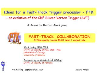
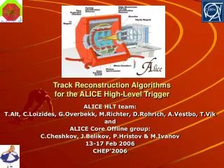
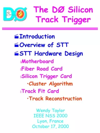
The DØ Silicon Track Trigger • Introduction • Overview of STT • STT Hardware Design • Motherboard • Fiber Road Card • Silicon Trigger Card • Cluster Algorithm • Track Fit Card • Track Reconstruction Wendy Taylor IEEE NSS 2000 Lyon, France October 17, 2000
Run II TeVatron • Fermilab, near Chicago USA • TeV collider • Bunch crossing time is 396 ns (eventually 132 ns) • Run II starts March 2001 • Expect of integrated luminosity in the first 2 years • DØ needs a trigger that • offers high reduction of backgrounds • allows efficient selection of rare process signatures • makes its decision fast (e.g., L2 has 100 s) IEEE NSS 2000
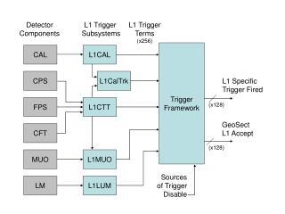
Detector L1 Trigger L2 Trigger 7 MHz 5-10 kHz 1000 Hz L2Cal CAL L1CAL FPS CPS L2PS L1 CTT Global L2 L2CFT CFT L2STT SMT L2 Muon L1 Muon Muon L2FW:Combined objects (e, m, j) L1FPD FPD L1FW: towers, tracks, correlations DØ Trigger System IEEE NSS 2000
Fiber Tracker Silicon Tracker 125 cm 50cm 20cm Solenoid DØ Tracking System IEEE NSS 2000
DØ Fiber Tracker CFT has 8 layers: A-H IEEE NSS 2000
DØ Silicon Detector SMT has 6 barrels and 4 layers IEEE NSS 2000
DØ SMT Barrel IEEE NSS 2000
Run II Physics at DØ • Decay signatures of top quark, Higgs boson, SUSY, and b quark include displaced tracks • Silicon Track Trigger identifies displaced tracks with high efficiency and purity in 25 s • STT will be installed one year after the start of Run II Impact parameter IEEE NSS 2000
L1CTT SMT preprocess SMT data find clusters associate clusters with L1CTT tracks L3 fit trajectories L2CTT Overview of STT Silicon Trigger Card (STC) Track Fit Card (TFC) Fiber Road Card (FRC) 3 custom VME boards mounted on common custom motherboard IEEE NSS 2000
CPU spare spare VBD spare spare terminator TFC STC STC STC STC STC FRC STC STC STC STC TFC spare terminator 1 2 3 4 5 6 7 8 9 10 11 12 13 14 15 16 17 18 19 20 21 Sector 1 Sector 2 STT Hardware Design Since most high-pT tracks stay in 30° SMT sector, 12 STT sectors are independent IEEE NSS 2000
STT Motherboard • Logic cards share requirements for internal and external interfaces • Mount logic daughter cards on common motherboard • 9Ux400 mm VME64x-compatible • 3 33-MHz PCI busses for on-board communications • Data communicated between cards via point-to-point links (LVDS) • Control signals sent over backplane • VME bus used for Level 3 readout and initialization/monitoring IEEE NSS 2000
STT Motherboard IEEE NSS 2000
Initialization/Downloading • Crate controller • Motorola MVME2302 200 MHz CPU • Initializes STT cards at power-up • Downloads lookup tables and FPGA/DSP code to STT cards • Notifies destination card of download • Information (e.g., DSP code) read from host computer over Ethernet • Information passed across VME backplane through motherboard’s PCI bus to destination card • I/O controller on destination card transfers data to destination • Gathers information from other cards for monitoring purposes IEEE NSS 2000
Fiber Road Card • Trigger receiver communicates with the trigger framework (SCL receiver card on motherboard) and broadcasts any control signals to the other cards (J3) • Road receiver receives tracks from the Level 1 CFT trigger • Trigger/roaddata formatter constructs the trigger/road data blocks and transmits this information to the other cards • Buffer manager handles buffering and readout to Level 3 • Implemented in 3 FPGAs IEEE NSS 2000
centroid pulse height strip cluster Silicon Trigger Card • Bad strips are masked (LUT) • Pedestals/gains are calibrated (LUT) • Neighbouring SMT hits (axial or stereo) are clustered using FPGAs programmed in VHDL • Axial clusters are matched to ±1mm-wide roads around each CFT track via precomputed LUT IEEE NSS 2000
Track Fit Card • Control logic (Altera FPGAs) maps each road to one of eight processors and handles I/O buffer management • Processor (TI DSP) receives 2 CFT hits and r- SMT clusters in road defined by CFT track • Lookup table used to convert hardware to physical coordinates • C program on DSP selects clusters closest to road center at each of 4 layers and performs a linearized track fit: IEEE NSS 2000
Hit Filtering Algorithm CFT H layer • To optimize track-finding efficiency, track purity and execution time, look for hits in all four layers but allow hits in only three out of four layers 2-mm road CFT A layer SMT barrels IEEE NSS 2000
Track Reconstruction • Formulate track equation in terms of hits (3 or 4 SMT + 2 CFT hits) • With 1 as reference, use residuals in computation • near-zero residuals allow use of integer arithmetic • Matrix is precomputed and stored in a lookup table IEEE NSS 2000
Beam Spot Correction • Track parameters computed wrt detector origin (0,0) • Impact parameter relevant to physics measured wrt collision (i.e., beam spot) • Beam spot position downloaded to STT on a run-by-run basis • Impact parameter correction performed in DSP where is beam position • Beam spot offset tolerance is 1 mm, within Tevatron specs IEEE NSS 2000
Performance • Impact parameter resolution of 35 m includes • beam spot size (30 m) • SMT resolution (15 m) • STT introduces negligible uncertainty to resolution • Monte Carlo calculation predicts 2 CFT tracks, 14 SMT clusters per sector and 3.7 clusters per track • Using above, queuing simulation predicts average STT latency is 25 s with negligible dead-time IEEE NSS 2000
Conclusions • STT represents custom solution to DØ’s trigger requirements for Run II • Decision time is 25 s with negligible dead-time • Design of motherboard as well as logic cards well under way • Card prototypes ready in 3 months for testing • FPGA and DSP programming progressing • STT will be installed and running by March 2002 IEEE NSS 2000