Download

1 / 17
190 likes | 229 Vues
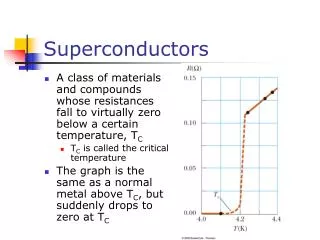
Explore the use of High-Tc Superconductors in fusion magnet systems for efficiency and reliability, detailing materials, magnet designs, and current developments.

E N D
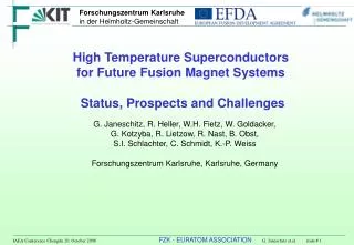
High Temperature Superconductors for Future Fusion Magnet Systems Status, Prospects and Challenges G. Janeschitz, R. Heller, W.H. Fietz, W. Goldacker, G. Kotzyba, R. Lietzow, R. Nast, B. Obst, S.I. Schlachter, C. Schmidt, K.-P. Weiss Forschungszentrum Karlsruhe, Karlsruhe, Germany
Long Term Fusion Magnet R&D ITER Demo / Proto Commercial Fusion Power Plant ≈2016 ≈2035 ≈2050 • Use of High-Tc Superconductors (HTS) allows • higher operating temperatures of 20 K to 77 K save investment higher efficiency • much lower effort for thermal shielding save investment • Higher thermal stability more reliable operation Need for Efficiency and Reliability
Efficiency optimization For commercial power plants it is essential to reduce power consumption ITP - refrigerator: 2 kW@ 4.4 K = 0.7 MW electric power ITER: 64 kW@ 4.4 K = 22 MW electric power DEMO: ??? MW electric power With a magnet system at 20 K a fusion machine would be more efficient with respect to electric power consumption for cryogenics. Great would be a machine with a superconducting magnet system at 65 K to 77 K! Cooling with liquid nitrogen would be possible! Above 20 K operation will be more reliable due to higher enthalpy
HgBaCaCuO TlBaCaCuO BiSrCaCuO YBaCuO BiSCCOYBCO LN2 LaSrCuO LaBaCuO Critical Temperature of Superconductors
HTS materials BSCCO and YBCO are promising Boundaries indicate jc = 0 => ultimate boundary Magnets for a Fusion-reactor
CuO2-Layers (s.c.) Spacing Layer CuO2 -Layers (s.c.) Charge Reservoir / Doping Problems of High-Tc Materials • Layered structures • Correct orientation necessary! • S.C. properties depend on doping • Grain boundaries are detrimental • Brittle materials (ceramics) • Long time R&D was necessary on the road to High-Tc cables Perfect crystal structure Oxygen doped For example: 90 K Superconductor YBa2Cu3O7 Oxygen binds electrons => holes are forming Cooper pairs
c-axis c-axis c - axis BSCCO: c-axis orientation is necessary - > rolled tapes • Application: HTS current lead demo for ITER (BSCCO)In the frame of the EU Fusion Development Program, a 70 kA HTS current lead with Bi - 2223/AgAu superconductor was developed and tested in FZK. This material is industrially available in long lengths. • Current lead consists of three parts: • Connection to low Tc S.C. HTS module (Bi - 2223/AgAu) Copper heat exchanger • 4.5 K 4.5 K - 65 K 65 K - 300 K
c - axis c-axis Composition of YBCO Coated Conductor (CC) On top a protection layer is placed The YBCO layer adopts the orientation of the buffer layer An oriented buffer layer avoids chemical YBCO / tape reaction A substrate tape is used for deposition c-axis c-axis c-axis YBCO offers higher B(T) but 3D orientation necessary Deviation by > 6 degree would already reduce jc significantly YBCO layer thickness ~ 1m The protection layer serves also as a normal conducting shuntwhen YBCO looses superconductivity (quenches).
Status of the YBCO Coated Conductor • Basic idea realized in 1996 for short length samples • anyhow major difficulties exist: • Homogeneity of long substrates • Buffer layer problem (complicated and time consuming) • Slow growth of YBCO film by sputtering or evaporation However, progress has been achieved by industry: up to 300 m high current coated conductor is available263 A for a 12 mm wide tape @ 77 K, self field (SuperPower)
Potential of HTS for Fusion and Challenges • Potential of High Temperature Superconductors • Much higher superconducting transition temperatures up to 105 K • Very high upper critical fields of the order of 100 T • High irreversible (operating) fields at higher temperatures • Excellent critical current densities up to high temperatures & magnetic fields • Challenges • Structural reinforcement is required • High conductor (cable) current is necessary for technical application • Hot spot temperature and quench are problematic (current extraction) • Bundling & cabling development to limit AC losses is mandatory
Structural Reinforcement HTS materials are brittle materials and thus strain sensitive.Therefore a structural reinforcement is necessary. As a consequence the necessary reinforcement reduces the engineering current density. • Conventional reinforcement is not possible, • HTS conductors need heat treatment at high temperature in oxygen atmosphere • Embedding of conductor in stainless steel is not possible before heat treatment • React-and-wind technology has to be used which limits the conductor size and the bending radius by the stress-strain behavior • The necessary reinforcement technology including react & wind has to be developed.
High Conductor (Cable) Current Which minimum conductor current is reasonable? Starting with the parameter of ITER TF coils (N*I = 9.1 MA, L = 0.349 H)the discharge voltage and time constant were calculated for different conductor currents As a compromise to limit both discharge voltage and time constant, 30 kA seems to be the minimum acceptable conductor current. 30 kA made of 40 A tapes (assuming Ic=50 A at 12 T & 50 K) would need 750 tapes!
For a 4 mm wide YBCO-CC with a critical current density of 2000 A/mm2, and a thickness of the copper stabilizer of 50 m, the hot spot temperature during a discharge ( = 21 s) will be about 120 K. • For a critical current density of 10000 A/mm2, a copper thickness of 300 m is required to limit the hot spot temperature to 130 K. Hotspot Temperature and Quench If the YBCO superconductor quenches the current has to be transferred to the protection layer which has to takes the current until the coil is discharged. The maximum temperature reached during quench is called hotspot temperature. The thickness of the Cu layer has to be adopted to limit the maximum temperature. => Depends also on discharge time !! Cu YBCO Substrate The increase of the critical current density in the YBCO by a factor of five results in an increase of the overall engineering current density of only a factor of two. =>This limits jc,eng!
Roebel bar conductor concepts already used in NbTi-LCT and NET subsize Applied in BSCCO-cable (SIEMENS) Bundling & cabling development to limit AC losses Cable-in-conduit conductor Nb3Sn strand (EM-LMI) AC-loss optimizedTFMC conductor: Multi stage twisted cable-in-conduit with central cooling channel, Rated current: 68 kA @ 11.8 T and 4.6 K AC - loss optimization is one of the most crucial points!
12 mm Roebel-Assembled-Coated-Conductor (RACC) Design and concept for low AC losses and high transport currents • Mechanical precision punching • Tool optimized for material and thickness • Sequential assembling to RACC structure Result of transport current measurements: Ic = 1020 A @ 77 K, self field (1 μV/cm) Result agrees well with expectations for a cable with 16 tapes.
Conclusions HTS allows higher temperatures and fields compared to classical superconductors However, today a high current HTS conductor for 30 kA is a real challenge with following critical items: • High current conductor layout • Conductor layout has to consider structure reinforcement and react&wind technology. • Main limitation is the large number of tapes which have to be used for cabling. • Hotspot temperature and quench • The copper stabilizer has to be large to limit the hot spot temperature which limits the engineering current density. • Bundling & cabling development to limit AC losses • Innovative cabling techniques have to be developed to limit AC losses. • A first 1 kA class Roebel type (RACC) cable was successfully fabricated by FZK from commercially YBCO coated conductor. • The achieved critical current agreed well with expectations. • The technique is reliable, suitable for long lengths & scalable for large currents.
Outlook • HTS R&D has to be adopted to fusion needs. • The minimum Goal should be a ~ 30 kA cable at 50 K / 12 T for future Fusion reactors.Main targets are: • Improvement of bundling and cabling techniques • Fusion conductor development in collaboration with industry • Design, manufacturing and test of a HTS Model–Solenoid (around 2012) • Design, manufacturing and test of a TF HTS Demonstration Coil in collaboration with industry (around 2015 to 2020) AcknowledgmentThis work, partly supported by the European Communities under the contract of Association between EURATOM and Forschungszentrum Karlsruhe, was carried out within the framework of the European Fusion Development Agreement. The views and opinions expressed herein do not necessarily reflect those of the European Commission.