Lý thuyết diode
1.12k likes | 1.59k Vues
Lý thuyết diode. Từ Vựng (1). anode bulk resistance = điện trở khối cathode diode ideal diode = diode lý tưởng knee voltage = điện áp gối linear device = dụng cụ tuyến tính load line = đường tải. Từ Vựng (2). maximum forward current = dòng thuận cực đại

Lý thuyết diode
E N D
Presentation Transcript
Từ Vựng (1) • anode • bulk resistance = điện trở khối • cathode • diode • ideal diode = diode lý tưởng • knee voltage = điện áp gối • linear device = dụng cụ tuyến tính • load line = đường tải
Từ Vựng (2) • maximum forward current = dòng thuận cực đại • nonlinear device = dụng cụ phi tuyến • Ohmic resistance = điện trở Ohm • power rating = định mức công suất • up-down analysis = phân tích tăng-giảm
Nội dung chương 3 3-1 Các ý tưởng cơ bản 3-2 Diode lý tưởng 3-3 Xấp xỉ bậc 2 3-4 Xấp xỉ bậc 3 3-5 Trounleshooting 3-6 Phân tích mạch tăng-giảm 3-7 Đọc bảng dữ liệu 3-8 Cách tính điện trở khối 3-9 Điện trở DC của diode 3-10 Đường tải 3-11 Diode dán bề mặt
Properties of Diodes ID (mA) IS VBR VD ~V (nA) Figure 1.10 – The Diode Transconductance Curve2 • VD = Bias Voltage • ID = Current through Diode. ID is Negative for Reverse Bias and Positive for Forward Bias • IS = Saturation Current • VBR = Breakdown Voltage • V = Barrier Potential Voltage Kristin Ackerson, Virginia Tech EE Spring 2002
Properties of Diodes The Shockley Equation • The transconductance curve on the previous slide is characterized by the following equation: • ID = IS(eVD/VT – 1) • As described in the last slide, ID is the current through the diode, IS is the saturation current and VD is the applied biasing voltage. • VT is the thermal equivalent voltage and is approximately 26 mV at room temperature. The equation to find VT at various temperatures is: • VT = kT • q • k = 1.38 x 10⁻²³ J/K T = temperature in Kelvin q = 1.6 x 10⁻¹⁹ C • is the emission coefficient for the diode. It is determined by the way the diode is constructed. It somewhat varies with diode current. For a silicon diode is around 2 for low currents and goes down to about 1 at higher currents Kristin Ackerson, Virginia Tech EE Spring 2002
Diode Circuit Models The Ideal Diode Model The diode is designed to allow current to flow in only one direction. The perfect diode would be a perfect conductor in one direction (forward bias) and a perfect insulator in the other direction (reverse bias). In many situations, using the ideal diode approximation is acceptable. Example: Assume the diode in the circuit below is ideal. Determine the value of ID if a) VA = 5 volts (forward bias) and b) VA = -5 volts (reverse bias) a) With VA > 0 the diode is in forward bias and is acting like a perfect conductor so: ID = VA/RS = 5 V / 50 = 100 mA b) With VA < 0 the diode is in reverse bias and is acting like a perfect insulator, therefore no current can flow and ID = 0. RS = 50 ID + VA _ Kristin Ackerson, Virginia Tech EE Spring 2002
Diode Circuit Models The Ideal Diode with Barrier Potential This model is more accurate than the simple ideal diode model because it includes the approximate barrier potential voltage. Remember the barrier potential voltage is the voltage at which appreciable current starts to flow. + V Example: To be more accurate than just using the ideal diode model include the barrier potential. Assume V = 0.3 volts (typical for a germanium diode) Determine the value of ID if VA = 5 volts (forward bias). RS = 50 With VA > 0 the diode is in forward bias and is acting like a perfect conductor so write a KVL equation to find ID: 0 = VA – IDRS - V ID = VA - V = 4.7 V = 94 mA RS50 ID + VA _ + V Kristin Ackerson, Virginia Tech EE Spring 2002
Diode Circuit Models The Ideal Diode with Barrier Potential and Linear Forward Resistance This model is the most accurate of the three. It includes a linear forward resistance that is calculated from the slope of the linear portion of the transconductance curve. However, this is usually not necessary since the RF (forward resistance) value is pretty constant. For low-power germanium and silicon diodes the RF value is usually in the 2 to 5 ohms range, while higher power diodes have a RF value closer to 1 ohm. ID + V RF Linear Portion of transconductance curve RF = VD ID ID VD VD Kristin Ackerson, Virginia Tech EE Spring 2002
Diode Circuit Models The Ideal Diode with Barrier Potential and Linear Forward Resistance Example: Assume the diode is a low-power diode with a forward resistance value of 5 ohms. The barrier potential voltage is still: V = 0.3 volts (typical for a germanium diode) Determine the value of ID if VA = 5 volts. RS = 50 Once again, write a KVL equation for the circuit: 0 = VA – IDRS - V - IDRF ID = VA - V = 5 – 0.3 = 85.5 mA RS + RF 50 + 5 ID + VA _ + V RF Kristin Ackerson, Virginia Tech EE Spring 2002
Diode Circuit Models Values of ID for the Three Different Diode Circuit Models These are the values found in the examples on previous slides where the applied voltage was 5 volts, the barrier potential was 0.3 volts and the linear forward resistance value was assumed to be 5 ohms. Kristin Ackerson, Virginia Tech EE Spring 2002
The Q Point The operating point or Q point of the diode is the quiescent or no-signal condition. The Q point is obtained graphically and is really only needed when the applied voltage is very close to the diode’s barrier potential voltage. The example 3 below that is continued on the next slide, shows how the Q point is determined using the transconductance curve and the load line. First the load line is found by substituting in different values of V into the equation for ID using the ideal diode with barrier potential model for the diode. With RS at 1000 ohms the value of RF wouldn’t have much impact on the results. ID = VA – V RS Using V values of 0 volts and 1.4 volts we obtain ID values of 6 mA and 4.6 mA respectively. Next we will draw the line connecting these two points on the graph with the transconductance curve. This line is the load line. RS = 1000 ID + VA = 6V _ + V Kristin Ackerson, Virginia Tech EE Spring 2002
The Q Point The transconductance curve below is for a Silicon diode. The Q point in this example is located at 0.7 V and 5.3 mA. ID(mA) 12 10 8 Q Point: The intersection of the load line and the transconductance curve. 6 5.3 4.6 4 2 VD(Volts) 0.2 0.4 0.6 0.8 1.0 1.2 1.4 0.7 Kristin Ackerson, Virginia Tech EE Spring 2002
Dynamic Resistance The dynamic resistance of the diode is mathematically determined as the inverse of the slope of the transconductance curve. Therefore, the equation for dynamic resistance is: rF = VT ID The dynamic resistance is used in determining the voltage drop across the diode in the situation where a voltage source is supplying a sinusoidal signal with a dc offset. The ac component of the diode voltage is found using the following equation: vF = vac rF rF + RS The voltage drop through the diode is a combination of the ac and dc components and is equal to: VD = V + vF Kristin Ackerson, Virginia Tech EE Spring 2002
Dynamic Resistance Example: Use the same circuit used for the Q point example but change the voltage source so it is an ac source with a dc offset. The source voltage is now, vin = 6 + sin(wt) Volts. It is a silicon diode so the barrier potential voltage is still 0.7 volts. The DC component of the circuit is the same as the previous example and therefore ID = 6V – 0.7 V = 5.3 mA 1000 rF = VT = 1 * 26 mV = 4.9 ID 5.3 mA = 1 is a good approximation if the dc current is greater than 1 mA as it is in this example. RS = 1000 ID + vin + V vF = vac rF = sin(wt) V 4.9 = 4.88 sin(wt) mV rF + RS 4.9 + 1000 Therefore, VD = 700 + 4.9 sin (wt) mV (the voltage drop across the diode) Kristin Ackerson, Virginia Tech EE Spring 2002
Từ Vựng (1) • Bias = phân cực • Capacitor-input filter = Mạch lọc ngõ vào (dùng) tụ • Choke-input filter = Mạch lọc ngõ vào (dùng) cuộn dây • Clamper = mạch kẹp • Clipper = mạch xén • dc value of signal = giá trị DC của tín hiệu • Filter = mạch lọc, bộ lọc • Half-wave signal = tín hiệu bán kỳ
Từ Vựng (2) • IC voltage regulator = Mạch ổn áp IC • Integrated circuit = IC = vi mạch = mạch tích hợp • Passive filter = mạch lọc thụ động • Peak detector = mạch tách sóng đỉnh • Peak inverse voltage = điện áp ngược đỉnh • Polarized capacitor = tụ (điện) hóa (học) = tụ có phân cực • Power supply = nguồn cấp điện
Từ Vựng (3) • Rectifier = mạch/bộ chỉnh lưu • Ripple = gợn • Surge current = dòng điện quá độ • Surge resistor = điện trở bảo vệ quá độ • Unidirectional local current = dòng điện cục bộ đơn hướng • Volatge multiplier = mạch nhân điện áp • Waveform = dạng sóng
Nội dung chương 4 4-1 Mạch chỉnh lưu bán kỳ 4-2 Máy biến thế 4-3 Mạch chỉnh lưu toàn sóng 4-4 Mạch chỉnh lưu cầu 4-5 Mạch lọc ngõ vào (dùng) cuộn dây 4-6 Mạch lọc ngõ vào (dùng) tụ 4-7 Điện áp ngược đỉnh và dòng quá độ 4-8 Một số vấn đề khác về nguồn cấp điện 4-9 Troubleshooting 4-10 Mạch xén và mạch hạn biên (limiter) 4-11 Mạch kẹp 4-12 Mạch nhân điện áp
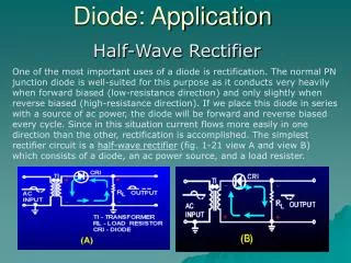
4-1 Mạch chỉnh lưu bán kỳ H. 4-1 (a) Mạch chỉnh lưu bán kỳ lý tưởng; (b) bán kỳ dương (diode ON); (c) bán kỳ âm (diode OFF)
4-1 Mạch chỉnh lưu bán kỳ (tt)Các dạng sóng lý tưởng Hình 4-2
4-1 Mạch chỉnh lưu bán kỳ (tt) • Điện áp ra đỉnh bằng điện áp vào đỉnh: • Giá trị DC của tín hiệu bán kỳ Vdc: • Tần số ra: fout = fin • Xấp xỉ bậc 2: Vp(out) = Vp(in) – 0.7V (diode Si)
A simple Battery charger-Example of a Rectifier • Can be used to charge a car battery from the alternator
4-2 Máy biến thế (Transformer) • Máy biến thế là 1 cặp cuộn dây có ghép hỗ cảm với nhau (để truyền năng lượng từ cuộn này sang cuộn kia bằng từ trường biến thiên). • Với số vòng dây khác nhau ta có máy biến thế tăng áp (step up) hay giảm áp (step down).
4-2 Máy biến thế (tt) Ký hiệu máy biến thế • The symbol for a transformer is a pair of the same loopy lines used for inductors, but close together. If the inductor has a core of a magnetic material, it is shown as a couple of lines between the coils. The number of turns in the coils will Be written nearby.
4-2 Máy biến thế (tt) Máy biến thế lý tưởng • Điện áp ở thứ cấp (secondary) V2: • Với: • N1: số vòng dây ở sơ cấp (primary) • N2: số vòng dây ở thứ cấp (primary) • V1: điện áp ở sơ cấp • Chú ý ta đang nói đến điện áp AC
4-2 Máy biến thế (tt) Mạch chỉnh lưu bán kỳ với máy biến thế
4-3 Mạch chỉnh lưu toàn sóng (tt)Các công thức • Giá trị DC hay trung bình Vdc: Vdc = 2Vp/ 0.636 Vp • Tần số ra: fout = 2fin • Xấp xỉ bậc 2: Vp(out) = Vp(in) – 0.7V (diode Si) Chú ý: Vp(in) = 0.5 V2 (V2 là điện áp ở thứ cấp vì ngõ ra có chấu giữa (center tap))
4-4 Mạch chỉnh lưu cầu (tt) Các công thức • Giá trị DC hay trung bình Vdc: Vdc = 2Vp/ 0.636 Vp • Tần số ra: fout = 2fin • Xấp xỉ bậc 2: Vp(out) = Vp(in) – 1.4V (diode Si) Chú ý: Chỉnh lưu cầu có ưu điểm hơn loại bán kỳ là ta có thể sử dụng toàn bộ điện áp ở thứ cấp
4-5 Mạch lọc ngõ vào (dùng) cuộn dây Hình 4-10 (a) Mạch lọc ngõ vào (dùng) cuộn dây; (b) mạch tương đương AC • Ý tưởng cơ bản: Nếu XL >> XC thì Vout XCVin/XL
4-6 Mạch lọc ngõ vào (dùng) tụÝ tưởng cơ bản (H.4-12, pp.108)
4-6 Mạch lọc ngõ vào (dùng) tụ (tt)Hiệu ứng của điện trở tải (H.4-13)
4-6 Mạch lọc ngõ vào (dùng) tụ (tt)Các công thức • Điện áp gợn đỉnh-đỉnh ở ngõ ra VR: Với: • VR = Điện áp gợn đỉnh-đỉnh • f = tần số gợn ( = fin với bán kỳ; = 2fin với toàn sóng) • C = điện dung
4-7 Điện áp ngược đỉnh PIV và dòng quá độ (xét lọc ngõ vào tụ) • H.4-18 • PIV = 2VP (b) PIV = VP (c) PIV = VP
Surge resistor Hình 4-19 Điện trở bảo vệ giới hạn dòng quá độ
Half-wave Full-wave Full-wave Bridge # of diodes 1 2 4 DC output voltage(**) Vin (peak) Vin (peak) (*) Vin (peak) DC diode current IL 0.5IL 0.5IL PIV (***) 2Vin (peak) 2Vin (peak) Vin (peak) Ripple Frequency f 2f 2f Comparison of Rectifier Circuits *With 1:2 transformer turns ratio; ** With Large C *** Peak Inverse Voltage (also with Large C)
4-10 Mạch xén và mạch hạn biên • Có 3 loại mạch xén: • Mạch xén trên (mạch xén dương) • Mạch xén dưới (mạch xén dương) • Mạch xén 2 mức độc lập (mạch xén kết hợp) • Mạch hạn biên hay kẹp diode • Chú ý: Tổng quát các mạch xén có phân cực
4-11 Mạch kẹp • Có 2 loại mạch kẹp: • Mạch kẹp dương • Mạch kẹp âm • Mạch tách sóng đỉnh-đỉnh: thường dùng cho diode tín hiệu nhỏ ở tần số cao
4-12 Mạch nhân điện áp • Thí dụ một số mạch nhân áp: • Nhân đôi điện áp (voltage doubler) • Nhân 3 điện áp (voltage tripler) • Nhân 4 điện áp (voltage quadrupler) • Nhân đôi điện áp toàn sóng (full-wave voltage doubler)
DC Power Supply Requirement Since this circuit has a significant dc component, with no dc component at the input, it can be used to produce a dc power supply. A dc power supply must be a nonlinear circuit.
DC Power Supplies, Peak Detector Power Supplies use a rectifier with a capacitor at the output. We start with a half-wave rectifier, since it is simpler. Show Fig. 3.32 from Sedra and Smith. This is a half-wave rectifier with a capacitor, which holds the peak value of the input source, vI(t).
DC Power Supplies, Peak Detector This circuit will hold the peak value only because there is nothing connected at the output. When we connect a load, something different happens.