Zenor Diode Diode Applications
Zenor Diode Diode Applications. ES230 Jack Ou. The Design of a Cell Phone Charger. c03f01. Still need to be filtered to get a DC voltage. Output of the transformer. c03f02. Short for Positive Voltages and Open for Negative Voltages. c03f03. Behavior of Ideal Diode. Ideal diode:


Zenor Diode Diode Applications
E N D
Presentation Transcript
Zenor DiodeDiode Applications ES230 Jack Ou
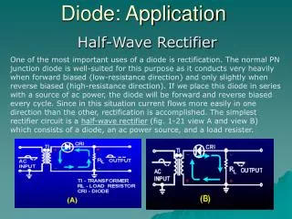
The Design of a Cell Phone Charger c03f01 Still need to be filtered to get a DC voltage Output of the transformer
c03f02 Short for Positive Voltages and Open for Negative Voltages
c03f03 Behavior of Ideal Diode Ideal diode: Vanode>Vcathode: Diode is on Vanode<Vcathode: Diode is off An ideal current experieincing Vanode=Vcathode, carries no current
c03f05 I/V Characteristics A short An Open A diode Vanode>Vcathode: Diode is on Vanode<Vcathode: Diode is off An ideal current experieincing Vanode=Vcathode, carries no current In practice, consider a slightly positive or negative voltage to determine the response of a diode.
c03f07 Example 1
c03f08 Example 2: An OR Gate Realized By Diodes
Example 3 c03f09 c03f09
c03f10 A Simple Cell Phone Charger Circuit (R1 is necessary) Another Application: Signal strength indicator
c03f11 A Limiter Circuit Question: How do you modify this circuit so that it passes only Positive portion of the waveform?
c03f13 Different Models of a Diode
Choosing a Diode Model Use the ideal model to develop a quick, rough understanding of a circuit. If the ideal model is not adequate, uses the constant voltage model, which is sufficient for most cases. Occasionally, we will use the exponential model
c03f14 Ideal Model versus Constant-Voltage Model
c03f15 Express ID1 and ID2 as a function of IS1, IS2 and Iin.