Download

1 / 18
1.26k likes | 6.2k Vues
Zener Diode Applications. Chapter 3. Overview. Zener Diodes Zener characteristics . Zener Diodes. Diode types Rectifier Zener . Lower Vz due to more heavily doped. Zener diode operates in the breakdown region. Zener Diode Basics. Made of silicon pn junction

E N D
Zener Diode Applications Chapter 3
Overview • Zener Diodes • Zener characteristics
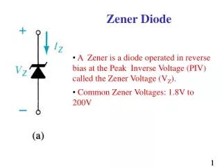
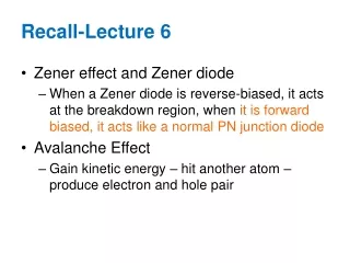
Zener Diodes • Diode types • Rectifier • Zener Lower Vz due to more heavily doped Zener diode operates in the breakdown region
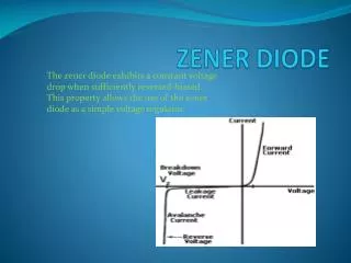
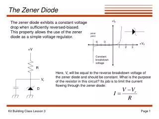
Zener Diode Basics • Made of silicon pn junction • Heavily doped to reduce the breakdown voltage • Used for operation in the reverse breakdown region • Called reverse break down (1.2<Vz<100) • Two types: Avalanche and Zener (both are Zener diodes) • Applications • Voltage regulator (the output voltage remains the same while changing the input voltage as long as IZK<IZT<IZM • Signal limiter
Characteristics Range at which voltage is maintained while current is changing Minimum current required to operate in breakdown region • Vz=Nominal Zener voltage; specific for IZT; typically has some tolerance • IZT=Zener test current; related to Vz • DVz=Change in Zener voltage • IZ=Current going through the diode for different values of Vz • ZZ=Zener impedance (DVz/DIz) • DIz= IZ - IZT • IZK=Minimum dc current • IZM=Maximum dc current • PD(max)=The max. power dissipated by the diode (IZM x Vz); IZM = PDmax / Vz • Power Derating (DF is derating factor (mW /oC) • PD(derated) = PD(max)@T1-DF(T2-T1) • TC=Temperature coefficient (% /oC) or (mW /oC) • DVz=DT xTC x Vz; DT is the change of temperature Iz Linear ZzT= Maximum current the diode can handle IZT In ideal model we assume Z is zero
Other Types of Diodes • Varactor diodes • Light-emitting diodes • Schottky diodes • PIN diodes
Depletion Region VR ; ; Plate Separation ; Capacitance Varactor Diodes • Operate in reverse bias • Dielectric is acting as capacitor • C capacitance, A=plate area, d=thickness
Varactor Diodes • Tuning Ratio (TR) • Nominal Capacitance is typically given (47 pF at VR=4 V) • Example: 1N5139 • Applications • Tuning circuits in TV to set the resonant frequency • Bandpass filter (R+(L||C))
Varactor Diodes Example • Accume • Vcont(min) = 2.9 • Vcont(max) = 29 • Hence • C2.9 = 55 pF • C29 = 17 pF fmin = 679 MKhz fmax = 1.22 MHz
Forward-biased Recombining free electrons with holes releases energy heat and light The process in which photons emit visible light is called electroluminescent The color of the LED depends on the added impurity (different wavelengths) If the color is Invisible Infrared Light-emitting Diodes (LED)
Light-emitting Diodes (LED) • Radiation intensity, Ie (power/steradian = W/Sr) • Sr is the unit of solid angular measurement • Irradiance = H = Ie / d2. (mW/cm2) General radiation pattern of a typical LED. Max Ie can be obtaine d from IF vs Ie graph
Example If H = 5, what is I?
Light-emitting Diodes (LED) • Photodiode • Reverse biased • Reverse current increases with light • Note that in rectifier diode, reverse current increases with temperature • Can also be used as variable resistor • Dark current is referred to the reverse current when there is no light • Example: MDD821 Note how the diode is Places in the circuit
Schottky Diodes • Used for fast switching and high frequency applications • Uses metal-to-semiconductor junction • V forward = 0.3 • No reverse leakage • Rapid response to changes (no hole current)
PIN Diode • Has an intrinsic region • It has a constant capacitance when reverse biased • When forward-biased current can be controlled through changing the resistance
Example 1 • The circuit above Vout should not change while Vin changes • What kind of diode do we need? Show how it is placed in the circuit. • Is the diode reversed or forward biased? • Model the practical diode of the diode assuming it is a 1N4733. Show the equivalent circuit after modeling. • Determine the range of the input voltage in which the output voltage stays the same. What is the minimum and max values of the output voltage? • Draw Vin – Vout voltage plot for the above points you calculated. • Use Multisim to verify your plot above.
Example 2 • What color of light is being emitted? • Assume IF for the light-emitting diode is 13 mA. What is the radiance of light-emitting diode? (Find H) • Find the sensitivity of the photodiode. What is its unit? • Find the reverse current through the photodiode