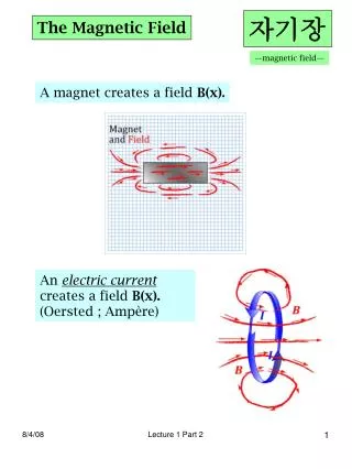
Download
1 / 25
250 likes | 393 Vues
CME Eruption at the Sun and Ejecta Magnetic Field at 1 AU . Valbona Kunkel Solar Physics Division, Naval Research Laboratory Collaborator: J. Chen vkunkel @ gmu.edu. April 15 2013 12th Annual International Astrophysics C onference.

E N D
CME Eruption at the Sun and Ejecta Magnetic Field at 1 AU Valbona Kunkel Solar Physics Division, Naval Research Laboratory Collaborator: J. Chen vkunkel@gmu.edu April 15 2013 12th Annual International Astrophysics Conference
“MAGNETIC FORCES”: MAGNETIC GEOMETRY OF CMEs • Dominant consensus from the 1980s and1990s (SMM era): CMEs are dome-like structures with rotational symmetry, not a thin flux rope Neither of the above 3D Geometry of CMEs–3 Part Morphology SMM Hundhausen (1999) Chen et al (1997) Illing and Hundhausen(1986) SOHO
INTRODUCTION: CME-FLARE PHYSICS • Key Questions in Coronal Mass Ejection (CME) Physics and New Answers: • What forces drive CMEs?—evolution of a CME and its B field from the Sun (to 1 AU) • What is the physical connection between CMEs and associated flares? • What is the energy source? Open physics issues—quantified • A Physical Model of CMEs: • The Erupting Flux Rope (EFR) model of CMEs: a quantitative theoretical model that correctly replicates observed CME dynamics—direct comparison with data: • CME position-time data from the Sun to 1 AU (STEREO) • in situB(t) and plasma measurements of CME ejectaat 1 AU (STEREO, ACE) • CME data and associated flare (GOES) X-ray (SXR) data (near-Sun processes) • Theme of This Talk: • What extractable physical information do data contain? Theory-data comparison at both ends of the Sun-Earth region and the intervening CME trajectory.
THEORY-DATA RELATIONSHIP • Physics Models: Characteristic Physical Scales • MHD is scale invariant—models are distinguished by characteristic scales • The EFR model---defined by MHD equations for macroscopic flux-rope dynamics • What determines the flux-rope motion?---3D flux-rope geometry and physical scales • Lorentz hoop force: • A 3D plasma structure: and evolve • Stationary footpoints: Sf = const and • Initial equilibrium conditions: • B0, MT0Acceleration time scale (Alfvenic) • How are these scales manifested in the data? a R Sf
Sf -SCALING OF FLUX-ROPE ACCELERATION Sf– Scaling A geometrical effect – a flux rope at t = 0 and accelerated by the Lorentz hoop force Directly manifested in data—3D geometrical effect Dynamical Scales Chen, Marque, Vourlidas, Krall, and Schuck (2006)
PHYSICAL INFORMATION IN DATA: Best-Fit Solutions • Extract physical information from observations—constrain the model by only the observed height-time data, Zdata(ti), and calculate the best-fit solution, Zth(ti) • Minimize the average deviation from the data (maximize the goodness of fit) • data, model solution, and uncertainty at the i-th observing time • Adjust Sf and to minimize D • A “shooting” method • Sf and calculated by the best-fit solution are the physical predictions of the EFR model constrained by the height-time data • The best-fit solutions can produce other physical predictions that can be tested • Hypothesis:
INITIAL-VALUE SOLUTIONS Input Parameters • Model corona—specified and unchanged • pc(Z), nc(Z), Bc(Z), Vsw(Z), Cd, • Observational constraints • Sf,Zdata(ti), ISXR(t) Model Outputs • Initial field and mass—calculated, intrinsic • Initial equilibrium conditions B0, Mt0, p0 • Initial-value solution • Sf,“shooting parameter” • Minimize D Sf, are physical predictions Z Sf
EMF: CME-FLARE CONNECTION X D = 1.3% Z0 = 2.5 x 10⁵ km Sf = 4.25 x 10⁵ km <E>max = 3.7 V/cm
12 September 2000 EMF: CME-FLARE CONNECTION • Best-fit and good-fit solutions yield in close agreement with X-ray light curve. • Predicted Sf is consistent with observation. Chen and Kunkel (2010) D = 1.3% Z0 = 2.5 x 10⁵ km Sf = 4.25 x 10⁵ km <E>max = 3.7 V/cm
SENSITIVITY OF FLUX INJECTION TO HEIGHT DATA Initial-value solution from Z0to 1 AU Chen and Kunkel (2010) The main acceleration phase manifests Alfven timescale B0 and MT0 Must be internally generated by a model The long-time trajectory is a stringent constraint on D = 1.4% Z0 = 8 x 10⁴ km Sf = 2.0 x 10⁵ km <E>max ~ 15 V/cm
CME-FLARE CONNECTION • Demonstrated for several CME-flare events: • The best-fit solutions constrained by height-time data alone yield —a physical prediction—in close agreement with ISXR(t) (temporal form) • The height-time data contain no information about X-rays—agreement is significant • Hypothesis and an interpretation • is a potential drop (super Dreicer) particle acceleration and radiation physical connection between CME and flare particle acceleration • Physical implications • The time scale of ISXR(t) is in the height-time data—via the ideal MHD EFR equations • The EFR equations capture the correct physical relationship between “M” and “HD” • Test with another observable quantity • Magnetic field at 1 AU as constrained by the observed CME trajectory data
6.1 New Start Plasma Physics Division PROPAGATION OF CME and EVOLUTION OF CME B FIELD STEREO Configuration 2007 Dec 24 A B Earth Observed B1AU and 3D Geometry [Kunkel and Chen 2010] • Best-fit solution is within 1% of the trajectory data throughout the field of view • If Zdata(t) is used to constrain the EFR equations, the model predicts B1AU(t) correctly • Arrival time earlier than observed; in this case, a 3D geometrical effect (Kunkel 2012)
SENSITIVITY OF B(1AU) TO SOLAR QUANTITIES Dependence of B(1 AU) on injected poloidal energy • Total poloidal energy injected: • Vary the flux injection profile while keeping Up|inj unchanged Best fit • |BCME| and arrival time at 1AU are not sensitive to the flux injection profile • BCMEfield and arrival time are most sensitive to injected poloidal magnetic energy Kunkel (PhD thesis, 2012)
MAGNETIC FIELD AND TIME OF ARRIVAL OF CME AT 1AU • Increase the total injected poloidal energy Up|inj by 10% • Calculate the best-fit solution • Calculate B(1 AU) and time of arrival of CME at 1 AU • Determine the goodness of fit for each solution Constant Injected Poloidal Energy Best fit
B(1 AU) AND ARRIVAL TIME AT 1 AU: INFLUENCE OF Bc • The overlying field Bc determines the initial Bp, initial energy, and Alfven time • Expect the 1 AU arrival time and B(1 AU) to be sensitive to Bc a R Sf
SUMMARY The EFR model equations • A self-contained description of the unified CME-flare-EP dynamics • Correctly replicates observed CME dynamics to 1 AU—a challenge for any CME model • It can be driven entirely by CME data to compute physical quantities: • — coincides with temporal profile of GOES SXR data (Chen and Kunkel 2010) • B field and plasma parameters at 1 AU — in agreement with data (Kunkel and Chen 2010) • B(1 AU) is not sensitive to the temporal form of ; it is sensitive to the total poloidal energy injected (Kunkel, PhD thesis, 2012; Kunkel et al. 2012) Physical interpretations of • is the electromotive force—physical connection to flares Implications –Space Weather • Given observed CME trajectory (position-time) data, it is possible to predict the magnetic field at 1 AU—there is sufficient information (Kunkel, PhD, 2012) • Accurate 1-2 day forecasting is possible if an L5 or L4 monitor exists
OPEN ISSUES Energy Sources • admits two distinct physical interpretations (Chen 1990; Chen and Krall 2003; Chen and Kunkel 2010) • Coronal source: injection of flux from coronal field via reconnection (conventional) • Subphotospheric source: injection of flux from the solar dynamo (Chen 1989, 1996) • Neither interpretation has been theoretically or observationally proven • Reconnection: physical dissipation mechanisms and large scale disparity • Subphotospheric mechanism: none has been calculated • Both are “external physics” in all current CME/flare models
OTHER MODELS • The EFR model should be applicable to flux ropes with fixed footpoints • models starting with flux ropes (Chen 1989; Wu et al. 1997; Gibson and Low 1998; Roussev et al. 2003; Manchester et al. 2006) • arcade models producing flux ropes (e.g. Antiochos et al. 1999; Amari et al. 2001; Linker et al. 2001; Lynch et al. 2009) • Does not apply to axisymmetric flux rope models—e.g., Titov and Demoulin(1999), Lin, Forbeset al. (1998), Kliem and Torok (2006) • They do not correspond to simulations (e.g., Roussev et al. 2003; Torok and Kliem 2008) • Mathematically, occurs in arcade models (e.g., Lynch et al. 2009) Titov and Demoulin (1999) Lynch et al. (1999)
PHOTOSPHERIC SIGNATURES? • Assumptions: • Coherent B field (space and time) • No dynamics • Schuck (2010) • Smaller A and longer • Same calculation (no dynamics) AGU Fall (2001) Lin et al. (2003)
OBSERVATIONAL SIGNATURES OF FLUX INJECTION • Schuck (2010) • Falsified the “flux injection hypothesis” • Consistent with the “reconnection hypothesis” • Starting point • Specified coherent field and time scale • No subsurface source of poloidal flux • No dynamical equations of motion for “injection” • No gravity (e.g., no Parker instability) • No convection zone medium through which “injection” occurs • No photosphere (i.e., no photospheric signature) • No reconnection physics or dynamics • No physical or mathematical basis to support either claim • A “Strawman” argument • The calculation is the same as Forbes (2001)
POLOIDAL FLUX INJECTION • Poloidal magnetic field is mostly in region—incoherent in dynamics Chen (2012, ApJ)
DYNAMICS OF POLOIDAL FLUX INJECTION Initial Simulation: Chen and Huba (2006) • 3D MHD code (Huba 2003) • A uniform vertical flux rope • Increase B field at the bottom • Introduce a horizontal flow (“convection” flow) • No gravity yet
PHOTOSPHERIC SIGNATURES • Pietarila Graham et al. (2009) –current magnetogram resolution insufficient to resolve small-scale magnetic structures • Cheung et al. (2010) –Simulation of an emerging flux rope; synthetic magnetograms • Photospheric data show small bipoles; scales are much smaller than the underlying emerging flux rope Cheung et al. (2010)
POST-ERUPTION ARCADES • Test the hypothesis that reformation of an arcade results from • Establishes the physical connection between CME acceleration and flare energy release Formation of Post-Eruption Arcades Quantities for comparison: temporal profiles v. Jc(t) Roussev et al. (2003) EUV+H Jc(t)