Download
1 / 67
670 likes | 856 Vues
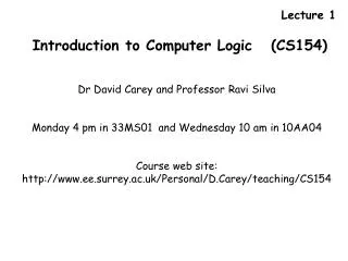
Lecture 1. Introduction to Computer Logic (CS154). Dr David Carey and Professor Ravi Silva Monday 4 pm in 33MS01 and Wednesday 10 am in 10AA04 Course web site: http://www.ee.surrey.ac.uk/Personal/D.Carey/teaching/CS154. Textbooks A number of textbooks are available

E N D
Lecture 1 Introduction to Computer Logic (CS154) Dr David Carey and Professor Ravi Silva Monday 4 pm in 33MS01 and Wednesday 10 am in 10AA04 Course web site: http://www.ee.surrey.ac.uk/Personal/D.Carey/teaching/CS154
Textbooks A number of textbooks are available • Digital Electronics, D.C. Green 5th Ed. 1997, published Longman (ISBN 0582317363, cost 18.99) • Introduction to Digital Electronics, J. Crowe and B. Hayes-Gill, 1st Ed. 1998, published Arnold, (ISBN 0340645709, cost 16.99) • Digital Fundamentals, T.L. Floyd, 8th Edition, published Prentice Hall, (ISBN 0130464112) • Introduction to Logic Design, A.B. Marcovitz, 1st Ed., 2002, McGraw-Hill, ISBN 0071123997, cost 36.46 (hardback). • Digital design principles and practices, J F. Wakerly, Prentice Hall (ISBN 0132128799)
Introduction to Boolean logic • · Introduction, Boolean Algebra, Symbolic representations, common logic gates • · Truth tables, Karnaugh maps, DeMorgan’s theorem, simplification of logic expressions • · Don’t care conditions • Combinational logic • · Half and full adders and subtractors, Multiplexers, demultiplexers and decoders • · Hazards, hazard detection and reduction • Programmable logic devices • · Read only memory ROM, PLA, PAL, other types of array structures • Number systems • · Binary, hexadecimal, binary-coded decimal, weighted and non-weighted systems • · Binary arithmetic, error coding and binary error detection, digital codes systems • Sequential Logic • · State of a system, latches and flip-flops, Asynchronous and synchronous modulo counters, • · Decimal Counter, Frequency Dividers, Shift registers • Digital components • · Digital displays e.g. seven segment displays, A/D and D/A converters The following material will be covered during the course.
Method of assessment 2005 • The course is assessed by means of one 2 hour examination at the end of the Spring semester – 75% • Two class assignments (25%) • Handed out: 31 Jan. (week 3) – Due back 16 Feb. (week 5) • Handed out: 28 Feb. (week 7) - Due back 16 Mar. (week 9)
A B Bulb Introduction to Logic gates This part of the course will introduce you to fundamentals of digital logic. We will use simple examples to show how basic logic gates can be constructed. We will also examine ways to simplify complicated circuits. As a first example consider the following lighting circuit with two switches A and B Q. Under what conditions will the bulb light ? A. When both switches are closed.
The key to this problem is to realise that the bulb will light ONLY when both switches A AND B are closed. This can be represented in a Truth Table. In binary logic we will denote a zero or low voltage by a digital 0 and a high voltage by a digital 1. This type of truth table is called an AND table. 2 Input AND truth table. 1 output Symbolically (Boolean) it is written as Y= AB and is read as ‘A AND B gives the output Y’
A B Bulb Here is another possible arrangement for the two switches. In this arrangement the bulb can light if either switch A or B is closed. This is an example of a circuit based on an OR gate. The 2 input OR table shows that if one or both inputs A and B are digital 1, the output is a digital 1. The Boolean expression for an OR gate is Y= A + B and is read as ‘Y is the output of A OR B’.
A Y B A Y B Y= A or A’ These logic gates are represented by AND gate Y = AB (also Y=AB) OR gate Y = A+B Both of these gates have 2 inputs and 1 output. A larger number of inputs are possible (see later). The NOT gate or inverter consists of a single input and the output is the opposite or complement of the input NOT gate For example 0 = 1 and 1 = 0 A Y
A Y B 1 1 1 1 h g f e d c b a Example 1. Consider a 2 input AND gate (A,B) and a pulse train Take A = 1 (always) and let the input of B be represented by this pulse train Since A is always 1 the output of the AND gate will depend on the input of B - in this case it will reproduce the pulse train. If A = 0, the Y = 0 for all times (a-h) Exercise 1.1: If the gate were replaced by an OR gate what would Y look like if (i) A=0 for all times and (ii) A= 1 for all times.
A A A0 = 0 (1) A + 0 = A (5) 0 0 A A A1 = A (2) A + 1 = 1 (6) 1 1 AA = A (3) A A A A AA = 0 (4) A + A = 1 (8) Some simple rules using logic gates AND gates OR gates A + A = A (7) These rules are very easy to work out so don’t try to learn them off - try to understand them There are some other rules worth noting
Here are some extra laws from Boolean algebra A + B = B + A (9) - this is known as the commutative law (OR) A B = B A (10) - this is known as the commutative law (AND) A + (B + C) = (A + B) + C = A + B + C (11) - this is known as the associative law (OR) A(BC) = (AB)C = ABC (12) - this is known as the associative law (AND) Laws (11) and (12) show that A(B + C) = AB + AC Exercise 1.2 : Prove A + AB = A use this result to show that A + AB = A + B
You may have noticed that there is a certain symmetry present in which rules of Boolean algebra appear in pairs. In a binary logic system it makes sense that there is a type of symmetry between the two operations and this symmetry is called Duality. Every equation has its dual which one can generate it by replacing the AND operators by ORs and vice-versa and the values 0 by 1s (and vice-versa). For example 1+A=1 is the dual of 0.A=0 A+A=1 is the dual of AA=0
Exercise 1.3 What is the dual of each of the following • A(A+B) = A • (ii) A B + B = A + B
Laws (11) and (12) deal with 3 - input logic gates. It is possible to create multiple inputs of both AND and OR gates (and other gates we shall study later). Note that the NOT gate has only 1 input. The symbol for a 3 input AND gate is and a 3 input OR gate The truth tables for both logic operations are given below A truth table with n inputs will have 2n rows. Note the ordering of the inputs - they follow the binary numbers - it is easier this way
To prove that two expressions are equal you need to prove that each element in the truth table is the same for both expressions. Example. Using a truth table determine of the two expressions for F and G are equal. F = A B + AC + B C and G = B + ABC
A B Y C So far we have dealt with individual logic gates. We shall now look at simple forms of combinational logic gates. Consider the following circuit - what is the Boolean expression for the output Y? Answer: Y = This is an example of a ‘sum-of-products’ expression and is comes from AND-OR logic
Constructing the truth table Take the circuit --> Boolean Expression --> Truth table It is also possible to go from the truth table to produce the Boolean expression and then produce the ( most simple) circuit
When do we get a logic 1. It occurs 3 times. The first case is when A is 0, B is 1 and C is 1. We can write this as A B C The second case is A is 1, B is 1 and C is 0, A B C Finally when A is 1, B is 1 and C is 1, which is A B C So we get a logic 1 output when and one of the 3 conditions is satisfied. So Y can be written as Y = A B C + A B C + A B C Question: Is this the same expression as we got before B(A + C)
What does this result demonstrate – how is this result different from ordinary algebra??
Lecture 2 In Lecture 1 we saw that if Y = AB then Y = AB + AB + AB + … This can be a useful result in manipulating expressions. In addition to the three gates already studied, there are other logic gates which perform different tasks. They are called NAND, NOR and XOR.
Y=AB The first is called NAND, and consists of an AND function followed by a NOT function For a 2 input NAND gate the Boolean expression is The circle at the output of the NAND gate denotes the logical inversion, (c.f. the inverter). Note that the over bar is a solid bar over both input values at once showing that AND function itself that is inverted, rather than each separate input.
Inherent in the operation of a 2 input NAND gate is the fact that one or more LOW inputs produces a HIGH output. There is a similarity here with a 2 input OR gate - in which one or more HIGH inputs produces a HIGH output – see table below. From this viewpoint a NAND gate can be used for an OR operation that requires one or more LOW inputs to produce a HIGH output. This is referred to as having active LOW inputs. (Assertion level logic) In this way the NAND gate can be viewed as a negative OR gate.
A + B AB NAND gate How do we make the inputs go negative i.e active LOW inputs. The inputs go ‘negative’ by using 2 inverters. Therefore we can represent a NAND gate as either • An AND gate followed by an INVERTER • An OR gate preceded by 2 INVERTERS AB = A + B - DeMorgan’s theorem Question: What is the dual of this expression??
Y=A+B The NOR function consists of the OR function followed by a NOT function For a 2 input NOR gate the Boolean expression is Again the bar is over both input values at once showing that OR function itself that is inverted, rather than each separate input. A NOR gate produces a LOW output when any of its inputs is HIGH. Only when all of its inputs are LOW is the o/p HIGH.
NOR gate With a NOR gate a HIGH o/p is produced only if all the inputs are LOW. From this viewpoint a NOR gate can be used for an AND operation with active LOW inputs. Therefore we can represent a NOR gate as either • An OR gate followed by an INVERTER • An AND gate preceded by 2 INVERTERS A + B AB A + B = AB - DeMorgan’s theorem
Combining gates when using inverters. There are times when it is necessary to convert from one logic function to another. Connecting an inverter to the output of a gate reverses the function of the initial gate
Y=A + B Y= A B Placing inverters at all the inputs changes AND to a NOR gate, also converts an OR gate to NAND. This leads to an alternative representation for the NAND and NOR gates below.
The effects of inverting both the inputs and the outputs. This is not used that often but does allow for a NAND gate to be converted to a NOR gate and vice versa.
AND gate NAND gate Summary of active HIGH and active LOW 2 input gates. OR gate NOR gate
AB = A + B - DeMorgan’s theorem A + B = AB - DeMorgan’s theorem We can see that each of the these two laws are duals of each other.
Note that DeMorgan’s theorems do NOT state that AB is the same as (A+B) Similarly A +B is NOT the same as A B These are common mistakes that are sometimes made.
AB = A + B - DeMorgan’s theorem A + B = AB - DeMorgan’s theorem There is a certain symmetry between these relationships. ‘ANDing’ or ‘ORing’ two variables together is the same as ‘ORing’ and ‘ANDing’ their complements. This means providing we have NOT gates available we can convert and circuit made from AND and OR gates to one constructed from OR and AND gates.
Dual Example. Draw a 2 input NAND gate and its dual and describe their outputs in terms of assertion level logic. In the NAND form the o/p is active LOW if both inputs are active HIGH. In the dualled form (based on an OR gate), the output is active HIGH if either input is LOW.
Example. The courtesy light of a car must go off when the door is closed and the light switch is off? What logic gate is required to implement this condition and what is an alternative way of looking at this circuit? ------------------------------------------------------------- The function can be implemented by an AND gate with active LOW inputs and outputs. Hence the o/p will go LOW (and the light OFF) when both inputs are LOW (door closed and switched off). Alternatively the light is ON (active HIGH) when either the door is open (active HIGH) or the switch is on (active HIGH). This would require an OR gate for implementation.
Summary AB = A + B - DeMorgan’s theorem A + B = AB - DeMorgan’s theorem Exercise 2.1: Using two truth tables prove DeMorgan’s theorem for three variables A, B and C Exercise 2.2 Write out the corresponding versions for 4 variables A, B, C and D.
Lecture 3 The final function is the XOR - Exclusive OR. Verbally it can be stated as ‘Either A or B, but not both’. For the 2 input XOR gate, a HIGH o/p will occur when one and only one i/p is logic HIGH. Note how this differs from an OR gate Y= A B
Y=AB + AB Y=AB + AB The XOR function can be made made using AND, OR and NOT gates. A B This is an example of AND-OR logic. We will discuss the importance of this later!! Exercise 3.1 Construct using AND, OR and NOT logic
In addition to 2 input NAND, NOR and XOR, multi input gates are possible. Here are the truth tables 3 input gates. The XOR gate is sometimes referred to as the ‘anything but not all’. The XOR gate is only enabled when there are an odd number of digital 1s Therefore the XOR can be viewed as an odd-bits check circuit.
Exercise 3.2. What is the output pulse train if (a) B = 1 and (b) B=0 0 0 0 0 A B 1 1 1 1 h g f e d c b a
Using NAND logic An obvious question is why do we use NAND or NOR gates rather than AND, OR and NOT since their implementation is easier? Answer: Many electronic gates naturally invert signals thus NAND is more natural than AND. Secondly, NAND and NOR are universal gates (also called Functionally Complete) since all the basic logical operations can be done with NAND or NOR gates.
A A All digital systems can be constructed from the fundamental AND, OR and NOT gates. It is also possible to construct them from NAND gates. The NAND gate is referred to as the universal gate for AND-OR logic. A NAND gate acting as an inverter The best way to analyse the next few circuits is by doing each logic operation in stages.
A AB B AB AB AB AB AB Two NAND gates acting as an AND gate
A A A B = A + B B B Three NAND gates acting as an OR gate
A A A B A + B B B Four NAND gates acting as an NOR gate
NAND gate There are several steps in converting from AND-OR to NAND logic. Recall from lecture 2 that So what do we do… 1. Draw an AND-OR logic circuit 2. Place a bubble at the output of each AND gate 3. Place a bubble at each input to the OR gate 4. Check logic levels Note we can remove the inverter as we will have a bubble on the input.
A B C D E A B C D The AND-OR logic circuit for Y = A B + C + D E is The same circuit using NAND logic is E
How do put a circuit into NAND form using Boolean algebra. Consider again, Y = A B + C + D E. If we the complement of this expression we obtain Y = A B + C + D E. It might tempting to use DeMorgan’s theorems here but that would not be of much use. Lets take the complement a second time to give us back Y. Y = A B + C + D E.
Exercise 3.3. Using only NAND gates construct circuits which perform the following representations. • A B C and A B C • A B + C D