Download
1 / 24
400 likes | 769 Vues
Higher order Laguerre-Gauss mode degeneracy in realistic high finesse cavities. Charlotte Bond, Paul Fulda, Ludovico Carbone, Keiko Kokeyama and Andreas Freise University of Birmingham. Amaldi , 11 th July 2011 LIGO-G1100821. Contents.

E N D
Higher order Laguerre-Gauss mode degeneracy in realistic high finesse cavities Charlotte Bond, Paul Fulda, Ludovico Carbone, Keiko Kokeyama and Andreas Freise University of Birmingham Amaldi, 11th July 2011 LIGO-G1100821
Contents • Laguerre-Gauss beams and higher order mode degeneracy • Coupling approximation using Zernike Polynomials • Simulation results • Adapting mirror surfaces for LG33
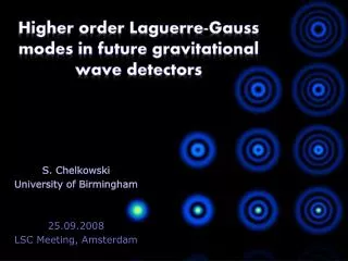
Advanced Virgo predicted sensitivity Thermal noise limit • Advanced detectors are expected to be limited by Coating Brownian thermal noise at around 100 Hz. • LG beams are the only candidate compatible with spherical mirrors.
Laguerre-Gauss 33 • The light intensity of the LG33 is more evenly spread around the optical axis than the fundamental Gaussian mode. • The LG33 beam more effectively averages over the mirror than LG00, reducing the effects of thermal noise.
Laguerre-Gauss modes Helical LG modes • A solution to the paraxial wave equation is: where up,l are a set of functions describing the beam shape: 3 2 l 1 0 0 1 2 3 p
Imperfect mirrors Input LG33 beam Distorted output beam with new LG modes
Laguerre-Gauss mode degeneracy LG phase shift compared to plane wave: Different orders have different resonance frequencies, BUT modes of the same order are resonant at the same frequency. LG00 is the only mode of order 0 and so is not degenerate. LG33 is one of 10 modes of order 9. LG0±9 LG1±7 LG2±5 LG3±3 LG4±1
Effect of LG33 degeneracy • The different distortions in each arm result in different circulating modes and a potentially large contrast defect.
Representing surface distortions: Zernike polynomials • Complete set of orthogonal polynomials which describe wave fronts over a unit disc: even odd
Analytical approach • Effect of mirror surface distortions can be described in terms of coupling from a mode Up,l in the incident beam to mode Up’,l’ in the reflected beam: • As the distortions are small we can approximate the exponential: • We find the only non-zero solutions to the approximation occur when: • Effect of mirror surface distortions can be described in terms of coupling into other modes. • Coupling from mode Up,l in the incident beam to mode Up’,l’ in the reflected beam: • We need an analytical description of the surfaces Zernike Polynomials
Coupling for order 9 LG modes As m ≤ n this also gives a limit on n of the Zernike polynomial required for significant coupling. m required for coupling from LG33(p=3, l=3) to the other order 9 LG modes
Cavity simulation • High finesse cavity simulated using Finesse with an input beam of pure LG33.
Example mirror map: ETM08 • To simulate realistic mirror distortions we use mirror maps measured from Advanced LIGO mirrors. We expect LG41 and LG25 to have large amplitudes in the cavity Example aLIGO mirror map, ETM08 showing the deviation from a perfect spherical mirror
Circulating field with mirror distortions Circulating field with ETM08 Circulating field with no astigmatism Pure LG33 input beam
Coupling analysis: ETM08 6.8 ppm into other order 9 modes Coupling into LG25 and LG41 ~ 10 times larger
Mirror requirements Requirement: power coupled from individual polynomials < 0.01 ppm Additional mirror requirements for ETM08:
Conclusion Conclusion: We can achieve a high beam purity with requirements for specific low order polynomials in the mirrors.
Overview Work done so far: • Identified particular distortions which cause order 9 coupling. • Demonstrated that a high beam purity is achievable by reducing specific polynomials. Outlook • Experimental tests of model. • Expand investigation to more complicated setups.
Thank you for listening [1] J.-Y. Vinet, Classical Quantum Gravity, 24, 3897 (2007) [2] B. Mours, E. Tournefier and J.-Y. Vinet, Classical Quan-tum Gravity, 23, 5777 (2006) [3] LSC Instrument Science White Paper 2010, LIGO-T1000416-v3 [3] A. Freise and K. Strain, Living Rev. Relativity, 13, 1 (2010), http://www.livingreviews.org/lrr-2010-1 [4] M. Born and E. Wolf, Principles of Optics, 7th (ex- panded) edition, (Cambridge University Press, Cam-bridge, UK, 1999) [5] ‘Zernike Polynomials and Their Use in Describing theWavefront Aberrations of the Human Eye’ (Stanford University, 2003) http://scien.stanford.edu/pages/ labsite/2003/psych221/projects/03/pmaeda/index.78, 082002 (2008) [6] S. Chelkowski, S. Hild and A. Freise, Phys. Rev. D, 79,html122002 (2009) [7] P. Fulda, K. Kokeyama, S. Chelkowski and A. Freise,Phys. Rev. D, 82, 012002 (2010) [8] A. Freise: ‘Finesse 0.99.8: Frequency domain interferom- eter simulation software’ (2008) Finesse manual available at http://www.gwoptics.org/finesse/
Azimuthal condition • Angular part: • Integrating with respect to ϕ for the even Zernike polynomial: • The only non-zero result occurs when one of the exponentials disappears before the integration. This occurs for: • We get the same condition for the odd Zernike polynomial.
Analytical approach • Angular integration gives π when m condition is met and ignoring phase factors. The final equation for the coupling coefficients is given by the following sum: Lower incomplete gamma function, for integer n: Where R is the radius of the Zernike polynomial and w is the beam radius
Beam size and polynomial order LG33 LG17 LG4-1
Central 160mm map region Can achieve small astigmatism amplitudes of: But coupling is still dominated by low order distortions.
Other map results Reduced maps on each mirror (ETM08 and ITM04): Results for other reduced maps applied to ETM: Majority (12 out of 15) < 1000 ppm Optimized beam radius results in 556 ppm with reduced ETM08 map.