Download
1 / 45
460 likes | 908 Vues
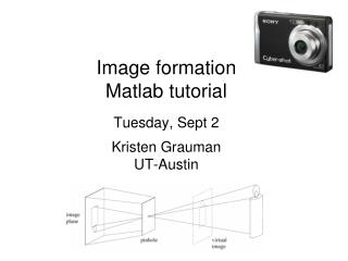
Image formation Matlab tutorial Tuesday, Sept 2 Kristen Grauman UT-Austin. Image formation. How are objects in the world captured in an image?. Physical parameters of image formation. Geometric Type of projection Camera pose Optical Sensor’s lens type focal length, field of view, aperture

E N D
Image formationMatlab tutorialTuesday, Sept 2Kristen GraumanUT-Austin
Image formation • How are objects in the world captured in an image?
Physical parameters of image formation • Geometric • Type of projection • Camera pose • Optical • Sensor’s lens type • focal length, field of view, aperture • Photometric • Type, direction, intensity of light reaching sensor • Surfaces’ reflectance properties
Image formation • Let’s design a camera • Idea 1: put a piece of film in front of an object • Do we get a reasonable image? Slide by Steve Seitz
Pinhole camera • Add a barrier to block off most of the rays • This reduces blurring • The opening is known as the aperture • How does this transform the image? Slide by Steve Seitz
Pinhole camera • Pinhole camera is a simple model to approximate imaging process, perspective projection. Image plane Virtual image pinhole If we treat pinhole as a point, only one ray from any given point can enter the camera. Fig from Forsyth and Ponce
Camera obscura In Latin, means ‘dark room’ "Reinerus Gemma-Frisius, observed an eclipse of the sun at Louvain on January 24, 1544, and later he used this illustration of the event in his book De Radio Astronomica et Geometrica, 1545. It is thought to be the first published illustration of a camera obscura..." Hammond, John H., The Camera Obscura, A Chronicle http://www.acmi.net.au/AIC/CAMERA_OBSCURA.html
Camera obscura Jetty at Margate England, 1898. An attraction in the late 19th century Around 1870s http://brightbytes.com/cosite/collection2.html Adapted from R. Duraiswami
Camera obscura at home http://blog.makezine.com/archive/2006/02/how_to_room_sized_camera_obscu.html Sketch from http://www.funsci.com/fun3_en/sky/sky.htm
Perspective effects • Far away objects appear smaller Forsyth and Ponce
Perspective effects • Parallel lines in the scene intersect in the image • Converge in image on horizon line Image plane (virtual) pinhole Scene
Projection properties • Many-to-one: any points along same ray map to same point in image • Points points • Lines lines (collinearity preserved) • Distances and angles are not preserved • Degenerate cases: – Line through focal point projects to a point. – Plane through focal point projects to line – Plane perpendicular to image plane projects to part of the image.
Perspective and art • Use of correct perspective projection indicated in 1st century B.C. frescoes • Skill resurfaces in Renaissance: artists develop systematic methods to determine perspective projection (around 1480-1515) Raphael Durer, 1525
Image coordinates Scene point Perspective projection equations • 3d world mapped to 2d projection in image plane Image plane Focal length Optical axis Camera frame ‘ ’ Scene / world points ‘’ Forsyth and Ponce
Homogeneous coordinates Is this a linear transformation? • Trick: add one more coordinate: • no—division by z is nonlinear homogeneous scene coordinates homogeneous image coordinates Converting from homogeneous coordinates Slide by Steve Seitz
Perspective Projection Matrix • Projection is a matrix multiplication using homogeneous coordinates: divide by the third coordinate to convert back to non-homogeneous coordinates Complete mapping from world points to image pixel positions? Slide by Steve Seitz
Perspective projection & calibration Perspective equations so far in terms of camera’s reference frame…. Camera’s intrinsic and extrinsic parameters needed to calibrate geometry. Camera frame
Perspective projection & calibration 3Dpoint(4x1) World to camera coord. trans. matrix(4x4) 2D point(3x1) Camera to pixel coord. trans. matrix (3x3) Perspectiveprojection matrix(3x4) = World frame Extrinsic: Camera frame World frame Intrinsic: Image coordinates relative to camera Pixel coordinates Camera frame
Weak perspective • Approximation: treat magnification as constant • Assumes scene depth << average distance to camera Image plane World points:
Orthographic projection • Given camera at constant distance from scene • World points projected along rays parallel to optical access
Pinhole size / aperture How does the size of the aperture affect the image we’d get? Larger Smaller
Adding a lens focal point f • A lens focuses light onto the film • Rays passing through the center are not deviated • All parallel rays converge to one point on a plane located at the focal lengthf Slide by Steve Seitz
Cameras with lenses F focal point optical center (Center Of Projection) • A lens focuses parallel rays onto a single focal point • Gather more light, while keeping focus; make pinhole perspective projection practical
Human eye Rough analogy with human visual system: Pupil/Iris – control amount of light passing through lens Retina - contains sensor cells, where image is formed Fovea – highest concentration of cones Fig from Shapiro and Stockman
Thin lens Thin lens Rays entering parallel on one side go through focus on other, and vice versa. In ideal case – all rays from P imaged at P’. Left focus Right focus Lens diameter d Focal length f
Thin lens equation • Any object point satisfying this equation is in focus
Focus and depth of field Image credit: cambridgeincolour.com
Focus and depth of field • Depth of field: distance between image planes where blur is tolerable Thin lens: scene points at distinct depths come in focus at different image planes. (Real camera lens systems have greater depth of field.) “circles of confusion” Shapiro and Stockman
Focus and depth of field • How does the aperture affect the depth of field? • A smaller aperture increases the range in which the object is approximately in focus Flower images from Wikipedia http://en.wikipedia.org/wiki/Depth_of_field Slide from S. Seitz
Depth from focus Images from same point of view, different camera parameters 3d shape / depth estimates [figs from H. Jin and P. Favaro, 2002]
Field of view • Angular measure of portion of 3d space seen by the camera Images from http://en.wikipedia.org/wiki/Angle_of_view
Field of view depends on focal length • As f gets smaller, image becomes more wide angle • more world points project onto the finite image plane • As f gets larger, image becomes more telescopic • smaller part of the world projects onto the finite image plane from R. Duraiswami
Field of view depends on focal length Smaller FOV = larger Focal Length Slide by A. Efros
Resolution • sensor: size of real world scene element a that images to a single pixel • image: number of pixels • Influences what analysis is feasible, affects best representation choice. [fig from Mori et al]
Digital cameras • Film sensor array • Often an array of charge coupled devices • Each CCD is light sensitive diode that converts photons (light energy) to electrons camera CCD array frame grabber optics computer
Digital images Think of images as matrices taken from CCD array.
width 520 j=1 i=1 500 height im[176][201] has value 164 im[194][203] has value 37 Digital images Intensity : [0,255]
Color sensing in digital cameras Bayer grid Estimate missing components from neighboring values(demosaicing) Source: Steve Seitz
Historical context • Pinhole model:Mozi (470-390 BCE), Aristotle (384-322 BCE) • Principles of optics (including lenses):Alhacen (965-1039 CE) • Camera obscura: Leonardo da Vinci (1452-1519), Johann Zahn (1631-1707) • First photo: Joseph Nicephore Niepce (1822) • Daguerréotypes (1839) • Photographic film (Eastman, 1889) • Cinema (Lumière Brothers, 1895) • Color Photography (Lumière Brothers, 1908) • Television (Baird, Farnsworth, Zworykin, 1920s) • First consumer camera with CCD: Sony Mavica (1981) • First fully digital camera: Kodak DCS100 (1990) Alhacen’s notes Niepce, “La Table Servie,” 1822 Slide credit: L. Lazebnik CCD chip
Summary • Image formation affected by geometry, photometry, and optics. • Projection equations express how world points mapped to 2d image. • Homogenous coordinates allow linear system for projection equations. • Lenses make pinhole model practical. • Parameters (focal length, aperture, lens diameter,…) affect image obtained.
Next Problem set 0 due Thursday turnin --submit harshd pset0 <filename> Thursday: Color • Read F&P Chapter 6