Download
1 / 105
1.08k likes | 1.54k Vues
CanSat 2012 Preliminary Design Review. Team 2134 - IEEE UCSD. CanSat 2012 PDR: Team 2134 (IEEE UCSD). 1. Presentation Outline. Introduction / Team Organization — Chris Warren Systems Overview — Chris Warren, Jeff Wurzbach Sensor Subsystem Design — Alex Forencich

E N D
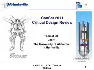
CanSat 2012 Preliminary Design Review Team 2134 - IEEE UCSD CanSat 2012 PDR: Team 2134 (IEEE UCSD) 1
Presentation Outline Introduction / Team Organization— Chris Warren Systems Overview— Chris Warren, Jeff Wurzbach Sensor Subsystem Design— Alex Forencich Descent Control Design— Jeff Wurzbach Mechanical Subsystem Design— Jeff Wurzbach Communication and Data Handling Subsystem Design— Alex Forencich Electrical Power Subsystem Design— Alex Forencich Flight Software Design— Chris Warren, Alex Forencich Ground Control System Design— Chris Warren, Alex Forencich CanSat Integration and Test— Jeff Wurzbach Mission Operations & Analysis— Chris Warren Management— Chris Warren 2 Presenter: Chris Warren CanSat 2012 PDR: Team 2134 (IEEE UCSD)
Team Organization 3 Presenter: Chris Warren CanSat 2012 PDR: Team 2134 (IEEE UCSD)
Acronyms • AGL – Above Ground Level • BPS – Barometric Pressure Sensor • CAN – CanSat System • CAR – Carrier Subsystem • DCS – Descent Control System • IMU – Inertial Measurement System • LAN – Lander Subsystem • MCU – Microcontroller Unit • PCBA – Printed Circuit Board Assembly • RTV – Room-temperature Vulcanizing Rubber • FSW – Flight Software • GSW – Ground Station Software • OTA – Over the Air • GCS –Ground Control Station 4 Presenter: Chris Warren CanSat 2012 PDR: Team 2134 (IEEE UCSD)
Systems Overview Chris Warren Jeff Wurzbach CanSat 2012 PDR: Team 2134 (IEEE UCSD) 5
Mission Summary • CanSat Objectives • Successfully leave the Payload Envelope of the rocket • Record and transmit telemetry every two seconds • Passively control descent rate as specified • Autonomously seperate into Carrier and Lander units at 91 meters above the ground • Carrier Objectives • Maintain a descent rate of 5 meters per second • Record atmospheric and position data onboard • Send recorded telemetry data to ground station • Lander Objectives • Maintain a descent rate of 5 meters per second • Record atmospheric and position data onboard • Land a large grade A hen's egg safely 6 Presenters: Chris Warren Jeff Wurzbach CanSat 2012 PDR: Team 2134 (IEEE UCSD)
Mission Summary (cont'd.) • Selectable Objective • Lander shall measure the force of impact on the ground at a sampling rate of 100 Hz • This data will be stored onboard for post-processing • Due to space and weight constraints, this is the easiest bonus objective to attempt • External Objectives • As a team, we wish to release as much open-source data, programming, and other system information as possible • We will publish information and experimental findings that proved to be important and useful in our project • This will serve as an aid and inspiration for other individuals/teams attempting similar system objectives 7 Presenters: Chris Warren Jeff Wurzbach CanSat 2012 PDR: Team 2134 (IEEE UCSD)
System Requirements – Cansat Mission 8 Presenters: Chris Warren Jeff Wurzbach CanSat 2012 PDR: Team 2134 (IEEE UCSD)
System Requirements – Cansat Mission (cont’d.) 9 Presenters: Chris Warren Jeff Wurzbach CanSat 2012 PDR: Team 2134 (IEEE UCSD)
System Requirements – Carrier 10 Presenters: Chris Warren Jeff Wurzbach CanSat 2012 PDR: Team 2134 (IEEE UCSD)
System Requirements – Lander 11 Presenters: Chris Warren Jeff Wurzbach CanSat 2012 PDR: Team 2134 (IEEE UCSD)
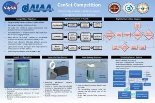
System Level CanSat Configuration Trade & Selection • Stacked Module Design (Selected) • Proven design • Easily constructed • Lower risk of binding during release phase • 360° antenna coverage is straight forward to accomplish • Sliding Module Design (Not used) • Simple retention mechanism • Higher sensitivity to tolerance stack up and misalignment • Possible antenna occlusion due to asymmetric design • Concentric Module Design (Not used) • High complexity geometry • Requires exotic PCB substrate to accommodate electronics • If designed correctly center of mass will not change dramatically after release • Parachute mount to inner module is simple, the outer module mount is comparatively complex 12 Presenters: Chris Warren Jeff Wurzbach CanSat 2012 PDR: Team 2134 (IEEE UCSD)
System Concept of Operations Pre-Launch Carrier Active Sleep Sleep Sleep Sleep Cansat will listen to XBEE, waiting for ground station to signal telemetry start MCU SENSOR (IMU / BPS / TMP) GPS OFF Sleep Active BUZZ XBEE Lander Active Sleep Sleep Sleep Sleep MCU SENSOR (IMU / BPS / TMP) GPS OFF Active BUZZ XBEE 13 Presenters: Chris Warren Jeff Wurzbach CanSat 2012 PDR: Team 2134 (IEEE UCSD)
System Concept of Operations (cont’d) Launch Carrier Active Sleep Active Active MCU will cycle, pulling necessary information from SENSOR package. Data retrieval and storage will be interrupt-based MCU SENSOR (IMU / BPS / TMP) GPS OFF Sleep Active BUZZ XBEE Lander Carrier and Lander will have near-exact flight hardware. Telemetry data from both units will be separated and parsed by the ground station Active Active Active MCU SENSOR (IMU / BPS / TMP) GPS OFF Active BUZZ XBEE 14 Presenters: Chris Warren Jeff Wurzbach CanSat 2012 PDR: Team 2134 (IEEE UCSD)
System Concept of Operations (cont’d) Apex / Deployment Carrier Active Sleep Active Active SENSOR data still polled, stored onboard, and sent via XBEE MCU SENSOR (IMU / BPS / TMP) GPS OFF Sleep Active CanSat will fall out of payload envelope. Drag chute (resting inside payload bay) will release, keeping CanSat at required descent rate BUZZ XBEE Lander Active Active Active MCU SENSOR (IMU / BPS / TMP) GPS OFF Active BUZZ XBEE 15 Presenters: Chris Warren Jeff Wurzbach CanSat 2012 PDR: Team 2134 (IEEE UCSD)
System Concept of Operations (cont’d) Descent A Carrier Active Sleep Active Active SENSOR data still polled, stored onboard, and sent via XBEE. MCU SENSOR (IMU / BPS / TMP) GPS OFF Sleep Active BPS pressure altitude will be monitored BUZZ XBEE Lander Once altitude transitions past 200 meters AGL, the secondary drag chute attached to the Carrier will be released Active Active Active MCU SENSOR (IMU / BPS / TMP) GPS OFF Active BUZZ XBEE 16 Presenters: Chris Warren Jeff Wurzbach CanSat 2012 PDR: Team 2134 (IEEE UCSD)
System Concept of Operations (cont’d) Descent B Carrier Active Active Active SENSOR data still polled, stored onboard, and sent via XBEE. MCU SENSOR (IMU / BPS / TMP) GPS OFF Active BPS pressure altitude will be monitored BUZZ XBEE Once altitude transitions past 91 meters AGL, the Carrier and Lander will separate Lander Active Active Active MCU SENSOR (IMU / BPS / TMP) GPS OFF Active Lander chute will deploy during separation BUZZ XBEE 17 Presenters: Chris Warren Jeff Wurzbach CanSat 2012 PDR: Team 2134 (IEEE UCSD)
System Concept of Operations (cont’d) Landing / Post-flight Carrier Sleep OFF Active Active OFF SENSOR data still polled, stored onboard, and sent via XBEE. MCU SENSOR (IMU / BPS / TMP) GPS ON Sleep ON IMU (containing the accelerometer) will be monitored at 100 Hz BUZZ XBEE After impact data is stored, Buzzer will be turned on, sensor package will be turned off, and the MCU and XBEE will sleep Lander Sleep Active OFF OFF Active MCU SENSOR (IMU / BPS / TMP) GPS ON ON Sleep MCU and XBEE will wake periodically to ping the ground station BUZZ XBEE 18 Presenters: Chris Warren Jeff Wurzbach CanSat 2012 PDR: Team 2134 (IEEE UCSD)
Physical Layout Isometric view of the Complete CanSat (covers not shown) Sectioned Front view of the Complete CanSat (covers not shown) 127mm 145mm 19 Presenters: Chris Warren Jeff Wurzbach CanSat 2012 PDR: Team 2134 (IEEE UCSD)
Physical Layout Carrier (cover not shown) Lander (cover not shown) 20 Presenters: Chris Warren Jeff Wurzbach CanSat 2012 PDR: Team 2134 (IEEE UCSD)
Physical Layout Front view of Carrier (cover shown) Carrier (cover shown) Note: Lander cover design is incomplete. 21 Presenters: Chris Warren Jeff Wurzbach CanSat 2012 PDR: Team 2134 (IEEE UCSD)
Launch Vehicle Compatibility • CanSat (Carrier + Lander) will be inserted into the payload envelope upside-down, with the initial drag chute closest to the base of the rocket stack • This allows the CanSat to fall out in the proper orientation • The CanSatdimensions will be within the required envelope, and will have a factor of safety built in such that the CanSat will fall out smoothly • 127mm • 145mm • We have ordered and received a LOC/Precision Minie-Magg rocket body • We will use this prior to our flight to ensure proper CanSat – Rocket integration and fit 22 Presenters: Chris Warren Jeff Wurzbach CanSat 2012 PDR: Team 2134 (IEEE UCSD)
Launch Vehicle Compatibility This rendering shows the Cansat assembly inside the specified reference payload envelope 23 Presenters: Chris Warren Jeff Wurzbach CanSat 2012 PDR: Team 2134 (IEEE UCSD)
Sensor Subsystem Design Alex Forencich CanSat 2012 PDR: Team ### (Team Name) 24
Sensor Subsystem Overview 25 Presenter: Name goes here CanSat 2012 PDR: Team ### (Team Name)
Sensor Subsystem Requirements 26 Presenter: Name goes here CanSat 2012 PDR: Team ### (Team Name)
Carrier GPS Trade & Selection • Selection: MT3329 • Extremely compact and lightweight • Internal antenna • High update rate • Binary protocol support for efficient storage and transmission of GPS data with no reprocessing 27 Presenter: Name goes here CanSat 2012 PDR: Team ### (Team Name)
Carrier Non-GPS Altitude Sensor Trade & Selection • Selection: BMP085 • Extremely compact and lightweight • Very accurate • Built in pressure sensor • Included in Mongoose IMU board 28 Presenter: Name goes here CanSat 2012 PDR: Team ### (Team Name)
Carrier Air Temperature Trade & Selection • Selection: BMP085 • Extremely compact and lightweight • Very accurate • Built in temperature sensor • Included in Mongoose IMU board 29 Presenter: Name goes here CanSat 2012 PDR: Team ### (Team Name)
Lander Altitude Sensor Trade & Selection • Selection: BMP085 • Extremely compact and lightweight • Very accurate • Built in pressure sensor • Included in Mongoose IMU board 30 Presenter: Name goes here CanSat 2012 PDR: Team ### (Team Name)
Lander Impact Force Sensor Trade & Selection • Selection: ADXL345 • Extremely compact and lightweight • Very accurate • Included in Mongoose IMU board 31 Presenter: Name goes here CanSat 2012 PDR: Team ### (Team Name)
Descent Control Design Jeff Wurzbach CanSat 2012 PDR: Team 2134 (IEEE UCSD) 32
Descent Control Overview • Carrier and Lander descent control will be accomplished with a parachute. • A hemispherical or an elliptical configuration shall be used ration to minimize mass, material, and volume. • A spill hole may be used for improved stability. • Rip-stop Nylon fabric will be used cut into gores and stitched into desired geometry. • Nylon cords will be used for suspension lines 33 Presenter: Jeff Wurzbach CanSat 2012 PDR: Team 2134 (IEEE UCSD)
Descent Control Requirements 34 Presenter: Jeff Wurzbach CanSat 2012 PDR: Team 2134 (IEEE UCSD)
Carrier Descent Control Strategy Selection and Trade • Material Selection – Rip Stop Nylon • Lightweight • Strong– proven to hold up humans when skydiving • Easy to work with • Bright orange is easily procured • We used nylon in last year’s competition • Parachute design performed marginally well • Flaws in last year’s implementation • Edges of the parachute crept up the shroud lines • Packing error caused the canopies to collapse during release phase • Using data / experience from last year to design and fabricate higher performance descent control parachutes 35 Presenter: Jeff Wurzbach CanSat 2012 PDR: Team 2134 (IEEE UCSD)
Lander Descent Control Strategy Selection and Trade • Using Rip Stop Nylon for Lander descent control • It makes sense for us to use only one material • Simplifies manufacturability • Nylon, as stated before, is proven to work • Bright pink selected for Lander descent control parachute 36 Presenter: Jeff Wurzbach CanSat 2012 PDR: Team 2134 (IEEE UCSD)
CanSat 2012 PDR: Team 2134 (IEEE UCSD) Descent Rate Estimates • Assumptions • Maximum system mass of 750 g • Mass split equally between Carrier and Lander • Mass of egg neglected for estimations • Pieces falling at terminal velocity • Air density at standard temperature and pressure • Configurations Estimates • Since mass of Carrier + Lander is double that of just the Carrier (or Lander), we can assume that the descent speed of the combined configuration is double that of the single pieces Presenter: Jeff Wurzbach
CanSat 2012 PDR: Team 2134 (IEEE UCSD) Descent Rate Estimates (cont’d) • Thus, we have decided to use the same parachute for both halves of the Cansat assembly • This will simplify design and manufacturability • However, since our CAD model has not yet been refined, we have not focused on nailing down the descent control design • The governing equations for parachute decent are well documented • The final mass budget we get from our final CAD design will drive those equations, the solution of which will be our finalized parachute design • All we really need is the parachute dimensions from those equations to move forward Presenter: Jeff Wurzbach
CanSat 2012 PDR: Team 2134 (IEEE UCSD) Descent Rate Estimates (cont’d) Presenter: Jeff Wurzbach
Mechanical Subsystem Design Jeff Wurzbach CanSat 2012 PDR: Team 2134 (IEEE UCSD) 40
Mechanical Subsystem Overview • Summary • Carrier design overview • Lander design overview • Egg Container and Protection System overview • PCBAs and electrical components • Material Selections 41 Presenter: Jeff Wurzbach CanSat 2012 PDR: Team 2134 (IEEE UCSD)
Mechanical System Requirements 42 Presenter: Jeff Wurzbach CanSat 2012 PDR: Team 2134 (IEEE UCSD)
Lander Egg Protection Trade & Selection • Selection: Neoprene Rubber and Expanding Foam (formed in the field, around egg to be launched) 43 Presenter: Jeff Wurzbach CanSat 2012 PDR: Team 2134 (IEEE UCSD)
Mechanical Layout of Components Trade & Selection • Principle metric for judging materials is workability. • This metric is key based on last year’s experiences of building the structures at the last minute • Parts have to machine-able with the tooling we have on hand • Table below shows the metrics considered and a brief description of the metric 44 Presenter: Jeff Wurzbach CanSat 2012 PDR: Team 2134 (IEEE UCSD)
Mechanical Layout of Components Trade & Selection 45 Presenter: Jeff Wurzbach CanSat 2012 PDR: Team 2134 (IEEE UCSD)
Material Selections • 3003 Aluminum sheet metal • Easy to work with (machines easily, takes bends well) • Readily available (carried by Home Depot and other local vendors) • Good strength to weight ratio • 40 mil High Impact Polystyrene • Vacuum formable • Allows low weight non-structural and low strength parts to be made • Low density foam • Low weight • Easily custom formable • Readily available • Neoprene/similar Rubber • Good shock absorption • Moderate weight • Augments the expanding foam 46 Presenter: Jeff Wurzbach CanSat 2012 PDR: Team 2134 (IEEE UCSD)
Carrier-Lander Interface Operational Model • 4 locking tabs hold the lander to the carrier • The carrier has a plate that turns and releases the locking tabs. • There are alignment tabs and pins that ensure the Lander does not rotate with the Carrier • Rotation is accomplished by rotary solenoid • Considering swapping a servo in to save weight. • Parachute for the lander will be stowed to the side of the lander • Pulled out during the separation phase by a drag line taped to the Carrier • Stowed here to prevent damage from moving parts 47 Presenter: Jeff Wurzbach CanSat 2012 PDR: Team 2134 (IEEE UCSD)
Carrier-Lander Interface Parts Carrier Parachute Foundation Mounting Nuts and Washers Rotary Solenoid Alignment Bracket Release Tabs Rotating Arm Lander Top Plate Planned Alignment Pins on Lander (not modeled yet) 48 Presenter: Jeff Wurzbach CanSat 2012 PDR: Team 2134 (IEEE UCSD)
Carrier-Lander Interface Operation Part Planned Motion of the Solenoid and Arm 49 Presenter: Jeff Wurzbach CanSat 2012 PDR: Team 2134 (IEEE UCSD)
Carrier-Lander Interface • Parachute Storage Parachute wrapped around the enclosure. Drag line (yellow) taped to the bottom of the Carrier 50 Presenter: Jeff Wurzbach CanSat 2012 PDR: Team 2134 (IEEE UCSD)