Extraction element layout Extraction parameters Current status of
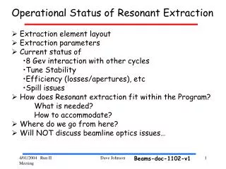
Operational Status of Resonant Extraction. Extraction element layout Extraction parameters Current status of 8 Gev interaction with other cycles Tune Stability Efficiency (losses/apertures), etc Spill issues How does Resonant extraction fit within the Program? What is needed?

Extraction element layout Extraction parameters Current status of
E N D
Presentation Transcript
Operational Status of Resonant Extraction • Extraction element layout • Extraction parameters • Current status of • 8 Gev interaction with other cycles • Tune Stability • Efficiency (losses/apertures), etc • Spill issues • How does Resonant extraction fit within the Program? • What is needed? • How to accommodate? • Where do we go from here? • Will NOT discuss beamline optics issues… Dave Johnson Beams-doc-1102-v1
Extraction element Layout (what’s where} Pbar Ext to RR Pbar Inj from RR Q1 = Q cos q Q2 = Q sin q QXR/bucker Abort Recycler Lamb. MI Lambertsons Extraction Straight Q2 = Q sin q NuMI Q1 = Q cos q Pbar Ext to TeV Dave Johnson
MI52 Extraction Region Physical Layout Q520 Q521 Septa Scanning Target Lambertson L Dave Johnson
Resonant Extraction parameters Present parameter space of the resonant extraction process is based upon an analytical analysis and numerical simulation carried out by John Johnstone (1993)*. I want to introduce some of the design parameters he used (without going into detail). • Initial tune separation, d , of 0.015 as determined by current in the main • Quad bus. • d = (53/2 - n) • Harmonic phase, z/2, as determined by the currents in the 2 families • of harmonic quads QC206 -> coos(z/2) and QC328 -> sin(z/2). where • z = tan-1(as/qc) with q = SRQT(qs2 +qc2) , where as and qc are the • orthogonal sin and cos quad contributions • Currently, we are using only the cos family which produces the phase • space orientation seen in the following slide *Beams-doc-092v2 and 096v1 Dave Johnson
Normalized Phase Space * Step size Position of septa * Used in Johnstone’s analysis Dave Johnson
Phase Space Orientation Mixing Qs and Qc Reduces maximum beam Size around the ring Current Operation, Qc only Dave Johnson
Parameters, continued • Step size, Dh, at the septa for the given by • Dh = 2 sin-1{ (4pd/(1+ (4pd))2 [-cos(z/2)+SQRT[1 + (4pd sin(z/2))2]]} • For the choices of d and z the current step size is ~3-4 mm • (as confirmed by the beam distribution on MW702 which is • approximately 180 deg in phase). Want to measure with TAR521 • The 0th harmonic octupole, l , is the integrated octupole field around • the ring from the MI quads and trim octupoles. Early in the design • (when IQC & IQD) were being constructed it was thought that the 0th • Harmonic octupole family would be needed. Currently only the • natural octupole content of the quads is being used. • Re-measure tune shift due to octupoles--- Dave Johnson
With the these parameters fixed (i.e. d , z , h, and l) the following • parameters are determined. • The septum offset, x sep , is determined by • x sep = SQRT(db/6l) [sin(z/2) + sin(Dh/2)] • was selected to be 16 mm, but was reduced to ~ 13 mm to reduce the • maximum beamsize elsewhere in the ring • This is determined by the closed orbit and the septa position, both • Relative the the straight section. Dave Johnson
Beam Separation at Septa The septa high voltage is 100 kV which produces a Kick of 218 ur each or 436 ur. Separation at Lambertson ~11 mm Dave Johnson
Impact of Septa High Voltage on 8 GeV Beam • Observations: • Orbit distortions • Tune shifts • Losses/ acceleration efficiency • Lattice perturbation 100 kV Beam Loss at 608 50kV Position at HP520 0kV Loss on MI52 kicker Dave Johnson
Impact of Septa High Voltage on 8 GeV Beam: Orbit Distortions • Measure orbit distortion at different offsets • with septa HV off and 100 kV • Kick required to produce observed rms distortion • Dx rms = (bb)1/2 Qrms • 2 sqrt(2) sin(pn) Measure ~76 ur effective kick per mm of rms Distortion. What septa voltage would be required to produce this kick? H.V. [kV] = Q[ur]g[cm]E[gev]/L[cm] Range from 1 to 2.8 kV effective leakage over the Range between 12 and 32 mm => 0.9 kV/cm gradient Dave Johnson
Impact of Septa High Voltage on 8 GeV Beam: Tune Shift Measure the tune as a function of position from the septa with the Septa HV at a constant 100 kV. The tune shift due to s single quad error may be estimated by: Dn = (1/4p)b q where q = G dl [m-1] br A tune shift of 0.01 could be generated by a quad strength of 0.003 [m-1] at a b of 40 m Dave Johnson
Impact of Septa High Voltage on 8 GeV Beam: Lattice Distortion Measure Lattice with Septa at 100 kV as a function of separation from septa. The rms distortion due to a gradient error appears as a distortion at twice the betatron phase D Db = 1 bqwhere q = G L [m-1] b2 sqrt(2) |sin(2pn)|br To produce a Db/b of .2 from a single gradient error located at the septa with a b of 40 m and a fractional tune of .42 requires a quad strength q of ~ .0067 [m-1] = > equivalent to about 6 amps on single harmonic quad at 8 GeV Dave Johnson
Impact of Septa High Voltage on 8 GeV Beam: What to do ? • Current mitigation • Move beam at HP520 to –18 mm (-15mm at septa) • when the septa HV is on and at nominal position • for extraction • Problem with this is that 8 GeV beam scrapes on • upstream end of first 52 kicker • Short term solution (testing) • Reduce offset to –10 to –12 mm at HP520 • Ramp septa from ~60 kV to 100 kV • Power supply modifications • Longer term solution • Fix position at HP520 for all cycles • Install vertical harmonic quads • Specialized three bump Dave Johnson
Flattop Orbits Used for Slow Spill High field orbit and locations of tight aperture: remove momentum offset on stacking cycle -> smooth the 120 energy orbit Use time bumps to establish extraction orbit – problems with total required corrector current -- see next Horizontal Vertical Dave Johnson
Losses during slow spill Losses on the septa and extraction Lambertson LN520E loss on downstream end of septa Losses at other tight apertures around the ring corrector quad moves large aperture quads Dave Johnson
Flattop Orbit: Correctors • Current situation • Currently 35 correctors with FT time bumps • Five 30 Amp supplies • Eight 20A are > 80% Imax • One 30A > 80% Imax • H corr saturate above 15A. ->(11 corr > 15 A) • Plans • MTF tests to add steel to reduce saturation effects (NuMI) • Add additional 30 Amp correctors • Quad moves to reduce corrector strength for slow spill • 453 card modifications (saturation lookup) Dave Johnson
Contributions to Horizontal tune at flattop • Main quad bus: Qh (52 quads: 32-84”/8-100”/ 12-116”) • Current 2826 amps for nom tune of 26.42 inc. to .485 requires ~ 4.4 amps • Implies Dn = 0.0136 /amp on the Qh bus. measured Dn = 0.0146 / amp • 2831 A => B’ = 163.08 kG/m => B’L/(br) = 0.1028 [m-1] • QXR: (Two 1 m air core configured in 0th harmonic) : Each magnet measured B’L = 0.0066 [T/amp] =>B’L/(br) = 0.165E-4 [m-1] Implies Dn = 0.00012 /amp (for 2 mag) , measured Dn = 0.001 /10 amp • Octupoles: in MI quads & 54 trim octupoles: 0th Harmonic • Trim: b3Leff=29.72 [kGm/m3/A] => B’”L/(br) = 0.418 [m-3] @ 10A • In Quad: 5 units (E-5 of B’) => B’”L/(br) = 0.45 [m-3] • produce amplitude dependent tune shift ~ x2 • Harmonic Quads: 2 families each with 8 magnets: 53rd Harmonic • B’L = 0.0269 [T/amp] => B’L/(br) = 0.91E-3 [m-1] 8 GeV & 0.67E-4 @ 120 GeV • {Implies Dn = 0.004 / amp (if powered individually and not in family) • measured Dn = 0.0037 +/- 0.00067 / amp} Dave Johnson
Flattop Tune Regulation Qh average current level changes of as little as 100 mA change extraction rate. => Dn ~ 0.0015 Multiple cycles within an asymmetric TLG due to changing bus resistance. 100 mA/div EE Support implementing a feedback system to measure changes in bus resistance by monitoring magnet power (i2r) Status: In progress Implemented-3/31 Dave Johnson
Slow spill regulation : QXR QC206 harmonic quad ramp QXR start level Ideal spill Dave Johnson
RF Spill What should we see on the RF spill monitor? With 30 bunches in the MI we should see600 ns burst of 53 Mhz (corresponding to the 30 bunches) repeating 11 us for the duration of the spill, currently 400 ms. What do we see ? Clumps of beam every which look to be harmonics of 60 Hz. What about this frequency Structure in the spill? Tune or orbit modulation or modulation if the tune distribution? Scope pict. from Peter Prieto Dave Johnson
RF Spill We want a constant rate of extracted beam dN/dt, modulo the MI filling factor (i.e number of bunches) obtained by smoothly moving the beam thru the ½ integer resonance stopband (QXR as 0th harmonic). The tune spread of the beam is dN/dn and dn/dt is the rate of change of the tune, where dn/dt = dn(0)/dt +dn(n)/dt , where dn(0)/dt is provided by QXR, and dn(n)/dt is unwanted tune modulation Then, RF Spill monitor located at F11 dN/dt = (dN/dn)*(dn/dt) Either a modulation in dN/dn or dn/dt will produce unwanted spill modulation Dave Johnson
RF Spill The tune spread, dN/dn, is assumed to be gaussian with contributions from nonlinearities in magnet fields (i.e. octupole which produce Dn ~ x2) energy spread (chromaticity, Dn ~ z Dp/p) -> large sync oscillations. The sync frequency at 120 GeV is 192 Hz. A large sync oscillation could modulate tune spread in presence of large chromaticity. A preliminary investigation by varying fs between 100 and 240 Hz didn’t change the observed freq modulation of the spill… The sources of unwanted tune modulation, dn(n)/dt need to be identified and reduced or eliminated. Some potential sources are: Power supply ripple (Main and trim supplies) Main Supplies (bend and quad bus) Trim supplies ( correctors and harmonic quads) Mechanical vibrations The remaining tune modulation will be reduced by the bucker system. This work has just began… Dave Johnson
RF Spill Quality What frequency structure is present in the spill ? An FFT was performed on the signal from the RF spill monitor… The predominate frequency was 120 Hz with nothing above 800 Hz 120 120 Hz 140 180 60 240 800 Hz Look at only low frequencies <250 Hz 2kHz Dave Johnson
RF Spill Recall, that the horizontal quad bus produced a measured tune shift of 0.0146 /amp => 70 mA will produce a 0.001 tune shift which is the equivalent to 10 amps on QXR (2 magnets). RFSPILL QXR 20A FS MHIERR 100 ma/div Beam Typical Spill with 1 turn 30 bunches: Dave Johnson
RF Spill Quality - the Bucker The Bucker system will be configured with two fast air core quads operating on the 0th harmonic of the tune and have the capability xx amps with a bandwidth of ~ 800 Hz. The current bucker algorithm uses a moving average of three cells in a feedback and learn. This was used successfully in Tev but has not been able to be used due to the large tune modulation. A study has been proposed by Peter Preito to characterize the frequency response of the MI during slow spill for selected freq between DC and 600 Hz. The purpose of this will be to generate coefficients to be used As a basis for the coefficients in the Bucker feedback algorithm. The new bucker algorithm is based upon a least mean square adaptive noise Canceling algorithm – already in use in MECAR. Software modifications Required to Implement the new algorithm Study time will be required… stay tuned… Dave Johnson
How do slow spill cycles fit within the Program • Minimize impact on Run II and stacking • Maximize beam to users • It will be an optimization of: • number of cycles per min in the timeline • the spill length • and bunch structure (i.e. number of bunches) • Current TLG module length is 3.6 sec…. can be shortened • The MI ramp length 2.78 sec (.5 sec inj , 1 sec FT) • S:HP3US ramp length is 3.6 sec (limiting factor) • S:HP3US ramp time can be remedied by three options: • new transformer (more volts) – 9 mo + $ • add 2nd supply- complicated • modify ramp (raise rest level/remove undershoot) • Keep rms < 900 Amps • time reduced to 1.7 sec. ramp + FT time (2.45 sec) Dave Johnson
Current Flattop timing for Resonant Extraction Compatible with Mixed-mode Operation MI Energy Flattop 1.18 sec -> 2.18 sec Dipole Corrector (time bump) • Harmonic quads • ½ int. comp • shrink phase space QXR Qh (26.42->.485) Fast 1.5 sec Slow Spill start 1.75 sec (400 ms) By removing the spill length could be increased by 250 –300 ms Pbar prod. (1.22 sec) Dave Johnson
Dedicated Slow Spill Cycle • Set tune to .485 at start of flattop.. • Assume 1 sec flattop length… • Min. delay from start of flattop ~ .32 sec (for dipole • and harmonic correctors to ramp) => max .68 sec spill • 1 batch - cycle time would be ~2.53 sec limited by • HP3US ramp time • 6 batches* - cycle time is still 2.78 sec limited by • MI ramp * Multibatch operation needs Booster notcher working Dave Johnson
Mixed Mode Cycle (with stacking) Could be used in either dedicated or mixed mode (depend on TLG module) 1 batch + 1 batch -> MI cycle 2.53 sec (set by HP3US FT) 1 batch + 5 batch -> MI cycle 2.78 sec In order to implement mixed mode we will run stacking and slow spill with same lattice in P1 and P2 or create dual flattop power supply ramps and define an additional clock event to uniquely define this mode stacking $29/$80/$89 (for the beamline only) slow spill $21/$30 mixed mode $21/$30/$80 (for Debuncher) and need multibatch injection !!!!! Dave Johnson
Summary • Resonant extraction is being established and turned off on a • regular basis by Operations via the Sequencer. • Initial parameters sufficient to provide resonantly extracted beam • to Experiments. these need optimized • Septa separation • Phase space orientation • Machine aperture / correctors / Large aperture quads • Instrumentation still needs to be fully commissioned and utilized • Resonant BPM, loss monitor for TAR521 • Spill stability / quality issues are beginning to be addressed • Power supply/ RF/ Bucker algorithms • Operational modes need to be defined (dedicated/mixed) • Most of the studies relating to optimizing resonant extraction may be carried out parasitically, but some will require dedicated study time with respect to Run II. • On-line resonant extraction simulation development continues Dave Johnson