Download
1 / 1
10 likes | 129 Vues
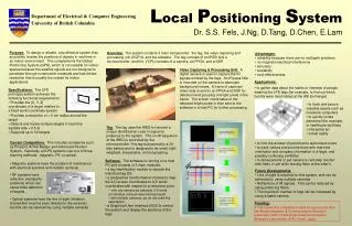
Z w. Rotation & translation. Y w. X w. (0,0). Z C. uc. Optical axis. vc. tag. M = (X,Y,Z). m= (x,y). Projection center. X C. Y C. L ocal P ositioning S ystem Dr. S.S. Fels, J.Ng, D.Tang, D.Chen, E.Lam. Department of Electrical & Computer Engineering

E N D
Zw Rotation & translation Yw Xw (0,0) ZC uc Optical axis vc tag M = (X,Y,Z) m= (x,y) Projection center XC YC Local Positioning SystemDr. S.S. Fels, J.Ng, D.Tang, D.Chen, E.Lam Department of Electrical & Computer Engineering University of British Columbia Purpose: To design a reliable, cost-effective system that accurately locates the positions of objects in real-time in an indoor environment. This complements the Global Positioning System (GPS), which is not suitable for indoor spaces because the satellite signals are not designed to penetrate through construction materials and has limited resolution that is usually too coarse for indoor applications. • Overview: The system contains 3 main components: the tag, the video capturing and processing unit (VCPU), and the software. The tag consists of an IRED and a microcontroller; and the VCPU consists of a camera, an FPGA, and a DSP. • Advantages: • reliability because there are no multipath problems • no magnetic/electrical interference • accuracy • scalability • cost-effectiveness Video Capturing & Processing Unit: A digital camera is used to capture the IR signals emitted by the tags. An IR-pass filter is mounted on the camera to attenuate background noises. A frame of captured video data is sent to an FPGA and DSP for detection and grouping of bright pixels in the frame. The screen coordinates of the detected bright pixels is then sent to the software in a host PC for further processing. • Applications: • to gather data about the habits or interests of people wearing the LPS tags (for example, to find out which booths were most visited at the ASI Exchange) • Specifications: The LPS prototype system achieves the following functional requirements: • Provides the (X, Y, Z) coordinates of a target relative to a fixed world coordinate system • to track and secure valuable assets such as notebook computers • to quickly locate personnel (for example, in healthcare facilities) • interactive art • virtual reality • Provides a resolution of < 5 cm radius around the target • Detects and tracks multiple targets in real-time (update rate < 0.5 s) • Supports up to 50 targets Tag: The tag uses the IRED to transmit a unique identification code to signal its presence to the system. The on-off sequence of the IRED is controlled by the microcontroller. The tag is powered by a 3V disc battery and is designed to be small, light- weighted, inexpensive, and long-lasting. • Current Competitors: This includes companies such as Pinpoint, Active Badge, and Advanced Position System. Generally, all LPS systems use one of three tracking methods: magnetic, RF, or optical. • Magnetic systems have the problem of interference with electrical systems and metallic surfaces. • to limit the access of personnel to authorized zones • to track visitors and provide them with real-time orientation and company information in a large, and possibly confusing exhibition • to allow parents or pet owners to remotely monitor their baby or pet while leaving them at the sitter’s • Software: The software is running on a host PC and consists of 3 main modules: • a tag identification module to decode the individual tag IDs • a perspective transformation module to map the 2-D screen coordinates to 3-D world coordinates with respect to a reference point • with one camera we calculate 3-D world coordinates using an assumed tag height • with multiple cameras, we do not need this assumption • a Graphical User Interface (GUI) to control the system and display the positions of the tags • Future Developments: • Line of sight is required for this system, and can be achieved by using multiple cameras • Reflections of IR signals. This can be reduced by using polarizing filters. • The maximum number of tags can be increased by using a faster camera. • RF systems have reflection (multipath) problems which can cause false detection of targets. • Optical systems have the line of sight limitation (transmitter must be seen directly by the receiver), but this can be resolved by using multiple cameras. • Funding: • This research is completely funded through a grant from the Media Integration & Communications Research Laboratory (MIC) of Advanced Telecommunications Research Laboratories (ATR), Kyoto, Japan.