Download
1 / 51
530 likes | 768 Vues
Learn about particles, forces, scalar and vector quantities, vectors classification, and vector operations in this introductory guide to the statics of particles.

E N D
What is a Particle: • body whose dimensions are negligible or whose dimensions approach zero, in a mathematical sense, in that it may be analyzed as a point mass. • When the dimensions of a body are irrelevant to the description of its position or the effects of the action of forces applied to it, the body may be treated as a particle
Statics of Particles Deals with: • The effects of concentrated forces on particles, • The addition of such forces and their resolution into components, • The determination of the resultant of a system of forces acting on a particle • The relationship between the forces acting on a particle in a state of equilibrium
Forces on a Particle Force: • that action/effect which tends to change the state of rest or uniform motion of a body • fully characterized by its magnitude and direction • direction is given by its point of application and line of action which is a straight line that is collinear with the force vector
Forces on a Particle (2) • Since particles are idealized as point masses, a system of forces acting on a particle will all pass through the point occupied by the particle. • Note that a system of forces that all pass through the same point are said to be concurrent. Thus if more than one force acts on a particle, the forces must be concurrent.
Scalar and Vector QuantitiesQuantities encountered in the study of Mechanics can be classified into Scalar and Vector quantities • Examples: Scalar quantities Have Magnitude only • temperature • distance • time • volume • density • speed • energy • mass • length
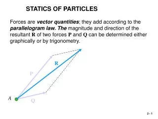
Vector quantities • Have Magnitude & Direction (line of action and sense) • must obey parallelogram law of addition • Examples: • force • moment • momentum • velocity • displacement • acceleration
Vectors • represented graphically by an arrow which defines the magnitude and direction of the vector. • Magnitude is indicated by the length of the arrow • Direction is given by the angle between a reference axis and the arrow's line of action • Sense is indicated by the arrow head. • Textbooks, represent vectors by boldface letters but in class, we will use an underline to represent vectors, e.g. vector A will be written as A.
Classification of Vectors • free vectors • sliding vectors • fixed vectors
Free Vectors • vectors that may be freely moved in space • i.e. their lines of action are not confined or associated with a unique line in space • Examples: • couples • displacement vector of a body which moves in space without rotation.
Sliding Vectors • Vector for which a unique line in space along which the vector acts must be maintained • Example: the external action of force on a rigid body (the force may be applied at any point along its line of action without changing its effect on the body as a whole - the principle of transmissibility).
Fixed Vector • one for which a unique point of application is specified and therefore the vector occupies a particular position in space • Example: the action of a force on a deformable or non-rigid body or a force acting on a given particle. • completely characterized by its point of application, its magnitude and direction (where the direction is defined by the line of action and the sense).
Equality of Vector • Fixed Vectors are equal if they have the same magnitude, direction and point of application. • Sliding Vectors must have the same magnitude, direction and line of action to be equal, but their point of application may differ. • Free Vectors must have the same magnitude and direction to be equal, but point of application and line of action may differ.
Equality of Vector B A C • A = B = C if and only if A, B, C are free vectors • A = B but is not = C if A, B, C are sliding vectors • A is not = B is not = C if A, B, C are fixed vectors • Two vectors are equal and opposite if they have the same magnitude but opposite directions • Null Vector: has zero magnitude in any arbitrary direction
Addition of Two VectorsParallelogram Law • sum of two vectors is obtained by constructing a parallelogram with the vectors at the two sides of the parallelogram. • The diagonal of the parallelogram represents the sum of the vector addition of the two vectors • vector addition is commutative: • P + Q = Q + P • vector addition is also associative: • P + Q + R = (P + Q) + R = P + (Q + R)
Subtraction of Two Vectors • Vector subtraction should be viewed as the addition of the corresponding negative vector • P - Q = P + (-Q)
Multiple Additions! • To obtain the sum of three or more vectors, apply the parallelogram law repeatedly to successive pairs of vectors until all the vectors are replaced by a single vector, the resultant
Triangle/Polygon Rule for Addition of Two or more Vectors • The Sum of two or more vectors acting on a body can be obtained graphically by arranging the given vectors in tip - to - tail fashion and connecting the tail of the first vector with the tip of the last one, provided that all the vectors are coplanar • Coplanar: vectors all lie in one plane. • Concurrent: vectors all act through one point.
Product of a Scalar and a Vector • The product of a scalar k and a vector P is a vector kP having the same direction as P (if k is positive) or a direction opposite to that of P (if k is negative), and whose magnitude is equal to the product of |P| (and the absolute value of k, where |P| is the magnitude of vector P
Resultant of Two Forces • The resultant of two forces acting on a particle is a single force which has the same effect on the particle as that of the two forces combined. • Such a resultant can be obtained from the parallelogram law for the addition of two forces. • Note that the parallelogram law is based on experimental evidence and cannot be proven or derived mathematically.
Resolution of a Vector into Components • This is the process of replacing a single force by two or more forces which collectively have the same effect on a particle as the the single force. • Theoretically, a force can be resolved into an infinite number of components. However, in most cases, components that act in specific directions (often along the x-, y- and z- coordinate axes) are desired.
Given that one of the two components of a force F is known, obtain the magnitude and direction of the other component • P is a known component of the given force F while the other component, Q is required: • Draw a line from the tip of P to the tip of F • Transfer Q to the point of application of P and F • Determine the magnitude of Q graphically or by using trigonometry
Given a force F and the lines of action of its components P and Q, obtain the magnitudes of P and Q: • Construct a parallelogram with F as diagonal and known lines of action as the sides • Sides of the parallelogram will give the required components P and Q
Trigonometric Solutions In general, • when a problem involves only three coplanar forces, draw the triangle of forces and use the sine and/or cosine rule to solve it. • If the force triangle is a right-angle triangle, then Pythagorean theorem may be applied • when a problem involves more than three coplanar forces or involves a 3-dimensional force system, resolve the forces into their rectangular components and solve using vector algebra
Sine and Cosine Rule Often results in simpler solutions than using vector algebra Cosine Rule • a2 = b2 + c2 - 2bc Cos A • b2 = a2 + c2 - 2ac Cos B • c2 = a2 + b2 - 2ab Cos C Sine Rule • a/sin A = b/sin B = c/sin C
Example 2.1 • Given: | Fab| = 100 KN | Fac| = 60 KN • Required: Magnitude and direction of the sum of the forces exerted by the cables (1) on the pylon (2) on the stadium Use: (1) graphical solution (2) Trigonometric solution
Example 2.2 • Given: Two forces with magnitudes as shown in the Figure. • Required: Magnitude and direction of the resultant force
Example 2.3 • Given: Two forces with magnitudes as shown in the diagram. • Required: Magnitude and direction of the resultant force
Example 2.4 • Given: Disabled automobile pulled by two ropes AB and AC. Tension in AB = 4000 N a = 20 degrees Resultant force acts along the axis of automobile. • Required: • Tension in rope AC • Magnitude of the resultant force of the two forces applied • Value of a such that the tension in AC is a minimum while R still acts along axis of automobile. What is the magnitude of Tac as well as the resultant force which still acts along axis of automobile.
Concept of Unit Vector • unit vector is a vector that has a magnitude of one/unity and mainly serves to identify the direction of a vector • unit vectors in the x-, y- and z- coordinate axes directions are designated as i, j and k, respectively Note that if a vector is divided by its magnitude, the result is a unit vector that acts in the direction of the vector
Rectangular Components of a Force in a Plane and in Space • components of a force which are parallel to the rectangular / Cartesian co-ordinate axes. • Components are perpendicular to each other and are said to be orthogonal • If Fx, Fy and Fz are therectangular components of a force F, then F = Fx + Fy + Fz Note: When working with coplanar system of forces, only two rectangular components (instead of three) are involved
Rectangular Components Contd… Recall that F =Fx + Fy + Fz If Fx , Fy ,and Fz are the scalar components of Fx , Fy ,and Fz , respectively, then F =Fxi + Fyj + Fzk wher i, j, and k are unit vectors in the x-, y- and z-coordinate directions.
Rectangular Components Contd... Given the vector F =Fxi + Fyj + Fzk the magnitude of F is the square root of the sum of squares of the orthogonal scalar components and is given by the expression The direction of F is given by the direction of the unit vector lF which has the same direction as F, where
Direction Angles and Direction Cosines • angles qx, qy and qz which a vector makes with the positive ends of the x-, y- and z-axes, respectively • the cosines of the direction angles (called direction cosines) are the rectangular scalar components of a unit vector acting in the direction of the vector.
Direction Angles and Direction Cosines Contd... • Hence lF = Cosqxi+ Cosqyj + Cosqzk Since lF is a unit vector, its magnitude is unity and Note that the relationship above implies that the three direction angles are are not independent. If two are known, the third can be obtained from the expression above
Direction Angles and Direction Cosines Contd... Recall that = Cosqxi+ Cosqyj + Cosqzk Since F =Fxi + Fyj + Fzk Hence
Resultant of a system of forces using their Rectangular Components The magnitudes of the rectangular components of the resultant force are given by the algebraic sum of the corresponding scalar components of the system of forces along a particular axis. Hence ifR = A + B + C + D, then Rx = Ax + Bx + Cx + Dx Ry = Ay + By + Cy + Dy Rz = Az + Bz + Cz + Dz
Given a System of Forces in Space acting on a Particle, determine the magnitude and direction of the Resultant force • Obtain the rectangular components of each force • Separately add all the x-, y- and z- components to obtain the components of the resultant force along the coordinate directions • Obtain the magnitude of the resultant force using its rectangular components • Obtain the direction of the resultant force by obtaining a unit vector lR in the direction of the resultant force. The rectangular components of lR give the direction cosines of the resultant force and hence the direction angles can be obtained
Given the magnitude of a force and two points along its line of action, express the force in terms of its rectangular components • Using the given two points, obtain a unit vector along the line of action of the force: • get the displacement vector from one point to the other; • get the magnitude of the displacement vector; • divide the displacement vector by its magnitude to get the unit vector • Multiply the unit vector by the magnitude of the force to obtain the force vector
Example 2.5 • Given: A vector of known magnitude |V| whose line of action passes through points A (x1, y1, z1) and B (x2, y2, z2) . The direction of the vector is from A towards B • Required: Components of the vector V in the three orthogonal directions. What are the direction cosines?
Example 2.6 • Given: F = (240N)i - (270N)j + (680N)k • Required: Magnitude and direction of F
Example 2.7 • Given: Spring AB & Post DA, with angle 30 degrees between post and spring. Tension in spring is |T| = 250 N • Required: (a) rectangular components of force exerted on plate at B; (b) direction angles of the force at B
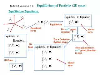
Equilibrium of Particles • A particle is said to be in equilibrium if the resultant of all the forces acting on it is zero. • This implies that if the force polygon is drawn for all the forces acting on a particle which is in equilibrium, the force polygon will close. • Algebraically, equilibrium condition is represented by R = SF = 0. Application of this equation must be accompanied by the relevant Free Body Diagrams
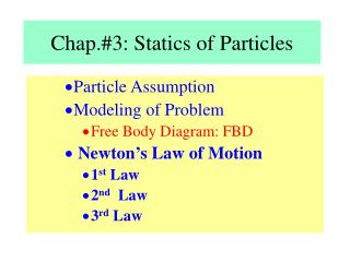
Free Body Diagrams • A diagram that shows a body or particle and all the forces acting on it. • All relevant dimensions, magnitudes and directions must be shown on the free body diagram. • All equations should be written based on the applicable free body diagrams
Example 2.8 • Given • Required: tension forces generated in ropes AB and AC
Example 2.9 • Given • Required:horizontal force "P" which the worker must exert on the rope to position the 50 kg crate directly over the transport vehicle
Example 2.10 • Given • Required:tensions in cables AC and BC
Example 2.11 • Required:Maximum value of F, Fmax and its corresponding angle of inclination, a • Given:Two ropes are tied together at C; maximum allowable tension in each rope is 2.5 kN
Example 2.12 • Given: a system holding a 60 lb crate in equlibrium • Required:tension in cables AB, AC & AD
Example 2.13 • Given:shear leg derrick used to haul 200 kg net of fish onto the dock • Required:compressive force in each of the legs AB & CB and the tension in cable DB, assuming that the force in each leg acts along its axis