Oscilloscopes
Learn how to safely operate and maximize the functionalities of the RIGOL DS1000 Series Digital Oscilloscope with comprehensive safety tips and usage guidelines.

Oscilloscopes
E N D
Presentation Transcript
RIGOL DS1000 Series Digital Oscilloscope Oscilloscopes Alex Jones COE 0501
Protect Yourself: Avoid contact with Voltage or Current Sources • Use shrouded test leads and alligator clips. • Leads: Connect to oscilloscope first; Connect/disconnect at source so loose lead is dead. • Connect probe to ground before connecting to high. Protect the Scope: • 400V maximum on input. • Use probes to reduce high voltages. • Be familiar with user’s guide. Safety Tips
Use Common Sense: Safety Tips • Use Proper Power Cord. Use the power cord designed for the instrument and authorized in your country only. • Connect and Disconnect Accessories. Do not connect or disconnect probes or test leads while they are connected to a voltage source. • Ground The Instrument. The oscilloscope is grounded through the grounding conductor of the power cord. To avoid electric shock the instrument grounding conductor(s) must be grounded properly. Before making connections to the input or output terminals of the instrument. • Connect The Probe. The probes’ ground terminals are at the same voltage level of the instrument ground. Do not connect the ground terminals to a high voltage. • Do Not Operate Without Covers. Do not operate the instrument with covers or panels removed. • Do Not Operate With Suspected Failures. If suspected damage occurs with the instrument, have it inspected before further operations. • Provide Proper Ventilation. • Keep product surfaces clean and dry
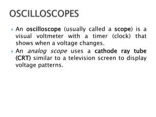
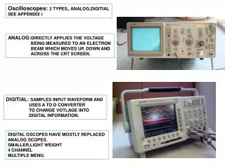
Oscilloscopes • Oscilloscopes display the relationship of Voltage vs. Timewaveformsfor analog and digital signals. • The display is like a dynamic plot. Therefore we must be able to adjust the scales and offsets of the “plot” of the waveform. • Voltage - set the Input / vertical scale factor • Time- set the horizontal / time scale factor • Position (Vertical and Horizontal) • Triggering - when should it start to draw? • Storage - keep a copy • Measurement - measure features of the waveform
Autoscale/ Triggering Vertical Scale Ground Inputs Calibration Front Panel Features Cursors Horizontal Position Measurement Vertical Position Horizontal Scale
Task - Front Panel • Draw a picture in your lab notebook of the front panel of your scope. • Every button, knob, and connector should be depicted and labeled. • Use an entire page of your lab notebook for this.
Task - Front Panel • On the next page of your notebook, make a list of the buttons, knobs, and connectors on the front panel. • As you learn about each item in the list, write a brief description of it in your notebook.
• This switch turns the oscilloscope on and off. Power Switch
• This adjusts the brightness of the display the display • If no trace is seen, it may be because the intensity setting is too low. Intensity Adjustment
• This connection may be used to ground probes. Ground Connection
• These connections are used to connect coaxial cable, probes, etc. to the oscilloscope. • The outside of the connector is grounded. Signal Inputs
£ • Make sure the input voltage level 400 V. • Connect a BNC cable or a probe to a channel input • Connect the other end of the cable or probe to the device to be measured. Connecting a Signal
Task - Calibration Signal • Connect a probe to channel 1. • Connect the red lead to the calibration signal below the display. • Push the Auto button. • Draw a picture of the resulting waveform in your lab notebook.
Input Selection • Use the push buttons to enable/disable eachchannel. • These also enable the “soft keys” next to the display
D V DC vs. AC Coupling • For digital signals we almost always want DC coupling. • AC coupling centers the signal on 0v • Digital signals swing between 0v and 5v
• Use the vertical volts/div knobs (located above the channel input connector) to scale the signal vertically on the screen. Vertical Scale
Task - Calibration Signal • Adjust the volts/div so that the entire calibration waveform is visible on the screen, and appears as large as possible. • Record the volts/div setting in your lab notebook. • Use the scope to measure the amplitude of the calibration waveform.
• Use the vertical position knob (located above the channel input connector) to position the signal vertically on the screen. Vertical Positioning
• Turn the time/div knob to adjust the sweep speed (time base). • The sweep speed has a range from 2ns to 50s. Time Base
• Turn the menu on or off next to the soft keys Menu On/Off
• Use the “delay knob” to move the signal horizontally. • Note the value displayed on the status line. Horizontal Positioning
Task - Calibration Signal • Adjust the time/div knob so that one period of the calibration waveform is visible. • You may need to turn off the menu • Record all time base parameters in your lab notebook. • Use the scope to measure the period of the calibration waveform. • Compute the frequency of the waveform.
• Use the trigger menu to assign a trigger source. • The choices are line, CH1, CH2 and external. Triggering Source
• Use this menu to choose a trigger sweep. • The choices are auto, normal, single Triggering Sweep Mode
• Use the level knob to set the trigger voltage. • The screen will display the trigger level in a horizontal line representing the trigger location. Triggering
1 Delay Triggering level + Slope - Slope Triggering
Custom Features Autoscale Voltage menu Time menu Cursor menu Storage
• Sets the Time Scale and Vertical Scale for all inputs Uses the highest active channel (1,2,ext) as trigger • Auto Scale
• Use this menu to make automatic measurements. • Voltage measurements include peak to peak Voltage, rms voltage, max voltage, etc. Measurements
Vp Vrms Vpp time Vrms = 0.707 Vp (Sine wave) Voltage Readings
• Use this menu to measure frequency, period, duty cycle, risetime, etc. Time Measurements
Period 1 T Hz f = T w = 2 × p × f rad/s ( t ) time Frequency and Period
• This menu brings up a list of cursor commands and activates the cursor knob. • The cursors can be used to measure specific voltages, times, etc. Cursor Menu
Storage Menu • This menu controls the storage features of the scope. • Load and store waveforms, overlay over each other