Medical Oscilloscopes
Medical Oscilloscopes. Medical Oscilloscopes. Cathode ray oscilloscope (CRO) basics: Many measurement are made easier by the CRO because it will display not only amplitude, but also time and wave shape relationships.


Medical Oscilloscopes
E N D
Presentation Transcript
Medical Oscilloscopes Cathode ray oscilloscope (CRO) basics: Many measurement are made easier by the CRO because it will display not only amplitude, but also time and wave shape relationships. Many medical instruments use the CRO to display physiological waveforms as an alternative to paper consuming strip-chart recorders. The heart of any oscilloscope is the cathode ray tube (CRT).
An electron gun at the rear of the tube emits a beam of electrons that is accelerated and focused by special electrodes beyond the gun When the accelerated electrodes strike the phosphor coated screen they will gave up their kinetic energy in the form of light. Without any other external influences the beam will impact exactly in the center of the screen. Patterns can be drawn on the CRT screen by deflecting the beam up and down and left and right of its normal path.
There are two basic types of CRT deflection system in common use in medical CRO’s: Magnetic deflection, and Electrostatic deflection
Electrostatic deflection CRT’s The electrostatic form consists of two pair of deflection plates : One for horizontal deflection, and Other for vertical deflection An electrical potential applied across either set of plates creates an electrostatic field that deflects the electron beam. The polarity of the potential determines the direction of the deflection, while its magnitude determine the amount of deflection. Most laboratory and service oscilloscopes use electrostatic deflection CRT’s because they can operate to very high frequencies.
Magnetic deflection CRT’s In the magnetic deflection system vertical and horizontal electromagnetic coils are positioned around the neck of the CRT, concentric to the electron beam path. Both coils are housed is a single assembly called a deflection yoke. Current flowing in the deflection coils create magnetic fields that deflect the electron beam. The frequency limitations of magnetic deflection system prohibit their use in laboratory and service oscilloscopes. Magnetic deflection is suitable for use in medical CRO’s
Medical Oscilloscopes Most medical oscilloscopes are of the Y-time type, meaning that the signal, a time varying voltage, is applied to the Y-axis, while a sawtooth time base signal is applied to the X- axis. This type of sweep allows us to view the waveform of the time domain signals such as the ECG and arterial pressure wave form. The horizontal sweep speed for the most medical oscilloscopes is 25mm/s or 50 mm/s, with some offering 100 mm/s
The medical oscilloscope differ from service and laboratory models in several principal ways: Horizontal sweep speed’ Vertical amplifier bandwidth, and CRT phosphor persistence.( long persistence time because the waveform viewed have such low fundamental frequencies). The medical CRO sweeps in subhertz range instead of kilohertz or megahertz. The amplifiers driving the vertical deflection system of the medical oscilloscope are limited in frequency response in order to eliminate or reduce its response to artifacts
Multibeam Medical Oscilloscopes The are no true multibeam cathode ray tubes, but a multi-trace display can be created by certain switching techniques and through the use of a gating amplifier.
In a gating amplifier system the vertical axis of the CRT is scanned at a fixed rate, usually 1.5-t0 25 kHz range, while, the horizontal axis is swept at 25 mm/s rate. The electron beam is turned off most of the time. The screen is turned on at specific times by pulses from the gating amplifier. The pulse repetition rate is controlled by the input voltage
Storage Oscilloscope The traditional oscilloscope uses a beam of electron to sweep the screen writing the waveform as it is deflected. The trace vanishes shortly after it is written onto the screen.
The principal sections of the storage oscilloscope are: 1- input amplifier, 2- Analog-to-digital converter (A/D), 3- scratch pad memory, 4- main memory, 5- digital to analog converter (D/A), 6- output amplifier, 7= control logic section. 8- some models include D/A converter to create a horizontal time base signal that is synchronize with the memory.
Analogue Amplifier The analogue amplifier serves both - to scale the amplitude of the output signal to the range of the oscilloscope and - to buffer the oscilloscope from the outside world. This stage tend to be a low gain (less than 10) transistor or IC operational amplifier. The gain is usually variable, so that the input signal amplitude may be selected properly.
A/D converter The A/D converter serves to create a digital binary word that is proportional to the applied signal amplitude. Eight and 10 –bit A/D converters are very common. A/D operation must be synchronize with a series pulses. The control logic section will generate a start pulse to initiate a conversion and the A/D will generate an end-of-conversion pulse to let the rest of the circuits when it is finished with the conversion cycle.
Memory The scratch pad memory is a shift register that holds one to four of the most recent data produced by the A/D converter. the main memory contains all the data appearing on the CRT Most medical non fade oscilloscopes use either 256, 512, 1024 eight-bit memory Both scratch and main memory are shift registers.
D/A converter In some models horizontal sweep is generated by a second D/A converter. A binary counter used to sequentially address memory locations also drive the horizontal D/A converter. The binary counter is driven by a clock signal, so the output lines increment by one bit for each clock pulse, The result of this action at the output of the D/A converter is that a few millivolts for every clock pulse received. When the counter over fellows, its output word goes from full scale( back to zero. The
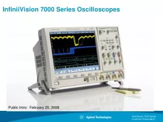
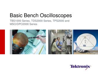
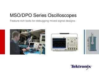
Modern Oscilloscopes Modern oscilloscope are based on a variety of digital and analog technologies and often include a microprocessor for signal processing and control functions
Touch screen oscilloscope The monitor uses a touch screen method for the selector “switches” Positioned along the edge of the display are a series of infrared (IR) sources (Light emitted diodes (LED’s)) operating in the IR region and IR detectors. The functions labels are either painted onto the CRT by the computor or affixed to the edge. When the operator touches the screen over any label, his or her finger interrupts one vertical and one horizontal beamcausing a unit pattern