Experimental Program on Concrete Column Behavior Under Load at Purdue University
This research focuses on the experimental evaluation of reinforced concrete columns subjected to varying loading conditions. Conducted collaboratively by UT Austin and Purdue University, the study investigates two specimen types: a bent column and a single column, each with specified reinforcement and strain gauge instrumentation. The concrete compressive strength utilized is 5000 psi. Detailed test setups, including loading directions and displacement history predictions, are provided to assess structural performance under predefined stress conditions. This investigation aims to enhance understanding of concrete column behavior and improve design paradigms.

Experimental Program on Concrete Column Behavior Under Load at Purdue University
E N D
Presentation Transcript
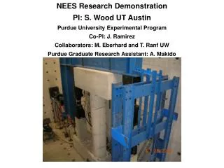
NEES Research DemonstrationPI: S. Wood UT AustinPurdue University Experimental ProgramCo-PI: J. RamirezCollaborators: M. Eberhard and T. Ranf UWPurdue Graduate Research Assistant: A. Makido
Purdue Experimental Program f’c = 5000 psi N = 0.08f’cAg (180 kips for Specimen 2 and 45 kips for Specimen 1)
Specimen 1- Bent Column Ag= 113 in2 ρg= 1.6 % ρs= 0.9 % (Specimen 1-1) = 0.6 % (Specimen 1-2) 16-#3 Bars 0.75 in. Cover ρg : reinforcement ratio ρs : volume ratio of spiral hoop to the core volume Spirals W2.9@ 1.25 in. (Specimen 1-1) W2.9@ 2.25 in. (Specimen 1-2) 12 in.
Specimen 2- Single Column Ag= 452 in2 ρg= 1.6 % ρs= 0.9 % (Specimen 2-1,2-2) = 0.6 % (Specimen 2-3) 16-#6 Bars 1.5 in. Cover ρg : reinforcement ratio ρs : volume ratio of spiral hoop to the core volume Spirals #3@2.5 in. (Specimen 2-1 and 2-2) #3@3.5 in. (Specimen 2-3) 24 in.
Loading direction Column Cross Section Longitudinal strain gage Transverse strain gage 6” 6” 3” 3” 2.5” d/2=12” d=24” 120” d=24” d/2=12” 2.5” Strain gage Instrumentation Plan
Loading direction Column Cross Section Potentiometer Steel Angle Bar 2.5” d/2=12” d=24” Potentiometer Instrumentation Plan 120” d=24” d/2=12” 2.5”
Construction of Specimen 1-1 Spiral Hoop with Instrumentation Casting of column
Construction of Specimen 2-1 Assembling Spiral Hoop Casting of column
Proposed Displacement History : Test Stage at Reno 16 8Δ’y 15 6.4Δ’y 4.8Δ’y 14 13 3.2Δ’y Pre-yielding 1.6Δ’y 1Δ’y Pre-cracking Δ’y: average measured displacement corresponding to longitudinal reinforcement strain gauges first yield