Proton Test Beam Experimental Program
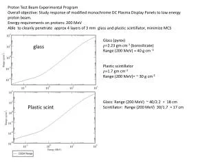
Proton Test Beam Experimental Program Overall objective: Study response of modified monochrome DC Plasma Display Panels to low energy proton beam. Energy requirements on protons: 200 MeV Able to cleanly penetrate approx 4 layers of 3 mm glass and plastic scintillator , minimize MCS.

Proton Test Beam Experimental Program
E N D
Presentation Transcript
Proton Test Beam Experimental Program Overall objective: Study response of modified monochrome DC Plasma Display Panels to low energy proton beam. Energy requirements on protons: 200 MeV Able to cleanly penetrate approx 4 layers of 3 mm glass and plastic scintillator, minimize MCS • Glass (pyrex) • =2.23 gm cm-3 (borosilicate) • Range (200 MeV) = 40 g cm -2 • Plastic scintillator • =1.7 gm cm-3 • Range (200 MeV)= ~ 30 g cm-2 • Glass: Range (200 MeV) ~ 40/2.2 = 18 cm • Scintillator: Range (200 MeV) 30/1.7 = 17 cm glass Plastic scint
Experimental Series 1 Beam parameters Energy: 200 MeV Collimation: 5 mm circular aperture Rates: 100-1000 Hz using 2X DRS4 (8 Readout lines instrumented) Structure: pulsed, 100 usecpulses, with ~msec separation Alignment of beam centroid to few mm Configuration Instrument section of 6 readout anodes x 14 HV lines. Readout with DRS4 waveform digitizers, 6-8 channels Panel VPA/VPC with ArCO2 99:1% Objectives Validate scintillatortrigger function, alignment & timing. Tune DAQ timing parameters. Validate DRS4 waveform digitization response to trigger c. Establish baseline response to proton induced ionization at initial Paschen discharge voltage Record pulses with fast waveform digitizers Tune HV to achieve triggered rate > 10 Hz Criteria for success Unambiguous observation of proton induced PPS pulses in temporal coincidence with pulsed beam and/or scintillatortrigger. Time window of 1 usec to allow for unknown cable and electronic propagation delays. Accumulation of recorded waveforms allowing measurement of pulse risetime and duration.
Experimental Series 2-A • Beam parameters • Energy: 200 MeV • Collimation: 5 mm circular aperture • Rates: O(103 -105) Hz cm-2 ( < 0.1 pA/cm2) • Structure: pulsed with 100 usec, bunch spacing few msec • Configuration • Instrument section of 12 readout anodes x 14 HV lines. • Readout with MDT minidaq • Panel VPA/VPC with ArCO2 99:1% • Objectives • Expand active area to 12 readout lines • Acquire triggered data to miniDAQ • Measure the hit distribution • Measurement of the arrival time • Criteria for success • Acquisition of multi-channel hit distribution at higher rate. • The triggered hit distribution width should correlate with the beam cross section
Experimental Series 2-B (HV scan) • Beam parameters • Energy: 200 MeV • Collimation: 5 mm circular aperture • Rates: O(103 -105) Hz cm-2 ( < 0.1 pA/cm2) • Structure: pulsed with 100 usec, bunch spacing few msec • Configuration • Instrument section of 12 readout anodes x 14 HV lines. • Readout with MDT minidaq • Panel VPA/VPC with ArCO2 99:1% • Objectives • Establish response as function of high voltage: • Triggered hit rate • Background hit rate • Acquire data in HV scan (2-5 V increments) allowing for HV response curve and efficiency • Translate to nearby pixel regions, repeat HV scan • Criteria for success • Measure response as a function of high voltage
Experimental Series 3-A (HV scan) • Beam parameters • Energy: 200 MeV • Collimation: 1 mm circular aperture • Rates: O(103 -105 ) Hz cm-2 ( < 0.1 pA/cm2) • Structure: pulsed with 100 usec, bunch spacing few msec • Configuration • Instrument section of 12 readout anodes x 14 HV lines. • Readout with MDT minidaq • Panel VPA/VPC with ArCO2 99:1% • Objectives • Similar to Series 2, but here use 1 mm collimator: • Establish response as function of high voltage for beam confined to 1 pixel region • Triggered hit rate • Background hit rate • Acquire data in HV scan (2-5 V increments) allowing for HV response curve and efficiency • Criteria for success • Acquisition of HV scan data coupled with scintillatortriggers enabling efficiency vs Voltage curves. • Data quality (timing, functioning of DAQ ) enables measurement of T0 pulse offsets (time of arrival) and timing jitter over range of voltages.
Experimental Series 3-B (Translation) Beam parameters Energy: 200 MeV Collimation: 1 mm circular aperture Rates: O(103 -105) Hz cm-2 ( < 0.1 pA/cm2) Structure: pulsed with 100 usec, bunch spacing few msec Configuration Instrument section of 12 readout anodes x 14 HV lines. Readout with MDT minidaq Panel VPA/VPC with ArCO2 99:1% Objectives Translate to nearby pixel regions in steps of 0.5 mm in RO axis to span an interval of 6 lines Criteria for success Acquire data to evaluate single line sensitivity Establish spatial resolution.
Experimental Series 4 Beam parameters Energy: 200 MeV Collimation: 1 mm circular aperture Rates: O(103 -105 ) Hz cm-2 ( < 0.1 pA/cm2) Structure: pulsed with 100 usec, bunch spacing few msec Configuration Instrument section of 12 readout anodes x 14 HV lines. Readout with MDT minidaq Panel VPD filled with CF4 Objectives Collect data with a panel Criteria for success Observation of signal correlate to beam trigger Measurement of arrival time distribution