Status of the SPL cryo-module development
440 likes | 601 Vues
Status of the SPL cryo-module development. V.Parma, TE-MSC (with contributions from WG3 members). SPL seminar, CERN 18th February 2010. Content. SPL architecture and parameters Work organisation Layout studies and machine sectorisation (vacuum+cryogenics)

Status of the SPL cryo-module development
E N D
Presentation Transcript
Status of the SPL cryo-module development V.Parma, TE-MSC (with contributions from WG3 members) SPL seminar, CERN 18th February 2010
Content • SPL architecture and parameters • Work organisation • Layout studies and machine sectorisation (vacuum+cryogenics) • Cryogenic scheme (for the prototype) • Supporting schemes • Next steps • Summary
Layout injector complex SPS PS2 ISOLDE PS SPL Linac4
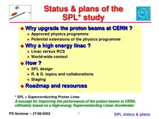
The SPL study Goals of the study (2008-2012): • Prepare a Conceptual Design Report with costing to present to CERN’s management for approval • This is the low power SPL (LP-SPL) optimized for PS2 and LHC 110 m 0.73 GeV 186 m 1.4 GeV 0 m 0.16 GeV 427 m 4 GeV 10 x 6 b=0.65 cavities 13 x 8 b=1 cavities 5 x 8 b=1 cavities High b cryomodules High b cryomodules Debunchers Medium b cryomodule To PS2 Ejection From Linac4 Length: ~430 m TT6 to ISOLDE LP-SPL beam characteristics
The SPL study (cont.d) • Study a 5 GeV and multi MW high power beam, the HP-SPL • Major interest for non-LHC physics: ISOLDEII/EURISOL/Fixed Target/Neutrino Factory ~500 m 5GeV 110 m 0.73 GeV 186 m 1.4 GeV ~300 m 2.5 GeV 0 m 0.16 GeV High b cryomodules Ejection 10 x 6 b=0.65 cavities 6 x 8 b=1 cavities 5 x 8 b=1 cavities High b cryomodules High b cryomodules Medium b cryomodule Debunchers To PS2 Ejection From Linac4 12 x 8 b=1 cavities to Eurisol Length: ~500 m TT6 to ISOLDE HP-SPL beam characteristics
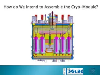
Cryo-module: Goal & Motivation Goal: • Design and construct a full-scale cryo-module prototype (part of the SPL Design Study) Motivation: • Develop technologies and demonstrate construction capabilityon a cryo-modulewith 8 β=1 cavities • Learning of the critical assembly phases (e.g. clean-room) • Enable RF testing on a multi-cavity assembly in real operating conditions (horizontal cryostat) • Investigate and acquire experience on cryogenic operation issues (e.g. process control)
Activity of WG 3 • Regular WG meetings since May 2009 • Web page: https://twiki.cern.ch/twiki/bin/view/SPL/CryoModules • Topics covered (or in progress): • Cryomodule longitudinal study • SPL mechanical layouts • Sectorisation issues • Cryogenic cooling schemes • Integration of RF Coupler • Cryo-module design: supporting systems, thermal shielding,... • Close collaboration with WG2 (cavities and ancillaries) • Relevant workshops 2009: • Workshop on Mechanical issues of SPL cavities/cryomodules: http://indico.cern.ch/conferenceDisplay.py?confId=68968 • Workshop on Cryogenic and vacuum sectorisation of the SPL: http://indico.cern.ch/conferenceDisplay.py?confId=68499 • Coming up soon (16-17 March): Review of the RF Couplers
Longitudinal mechanicallayouts «Continuous» vs. «fullysegmented» cryostat SPL layouts Continuous cryostat "Compact" version (gain on interconnections): 5 Gev version (HP):SPL length = 485 m (550 m max availablespace) "Warm quadrupole" version (withseparatecryoline): 5 Gev version (HP):SPL length = 535 m (550 m max availablespace)
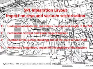
Outcome of workshop on cryogenic and vacuum sectorisations of the SPL (November 9-10, 2009) Cryogenics and vacuum sectorisation
Possible cryogenic feeding:“continuous” cryostat Cryo-plant 1.7% tunnel slope CIB 10 β=0.65 + 5 β=1 cryo-modules 6 β=1 cryo-modules 17 β=1 cryo-modules + 2 demodulators Isolde extraction Eurisol extraction CIB Cryogenic Interconnect Box Cryo Unit Cryogenic bridge
“continuous” cryostat • “Long” and “continuous” string of cavities in common cryostat • Cold beam tube • “straight” cryogenic lines in main cryostat • common insulation vacuum (between vacuum barriers, if any present) String of cryo-modules between TSM Technical Service Module (TSM) Cold-Warm Transition (CWT) Insulation vacuum barrier Warm beam vacuum gate valve
Possible cryogenic feeding:Cryogenic Distribution Line Cryo-plant 1.7% tunnel slope CIB 10 β=0.65 + 5 β=1 cryo-modules 6 β=1 cryo-modules 17 β=1 cryo-modules + 2 demodulators Isolde extraction Eurisol extraction CIB Cryogenic Interconnect Box Cryo-module Units Cryogenic Distribution Line
“segmented” cryostat • Cryostat is “segmented”: strings of (or single) cryo-modules, 2 CWT each • Warm beam zones • Cryogenic Distributio Line (CDL) needed • Individual insulation vacuum on every string of cryo-module (Vacuum Barriers, w.r.t. CDL) Cryogenic Distribution Line (CDL) String of (or single) cryo-modules Technical Service Module (TSM) Cold-Warm Transition (CWT) Insulation vacuum barrier Warm beam vacuum gate valve
Main issues • Machine availability: • “work-horse” in the injection chain • Reliability of built-in components and operational risks • Typical faults expected on: cavities, couplers, tuners... • Operation with degraded performance (cavities, optics, leaks...) • Maintainability: • Warm-up/cool-down . Time and reliability. Need for partial or complete warm-up of strings to replace built-in components or even one cryo-module • Accessability of components for regular maintenance or repair • Design complexity of compared solutions • Operational complexity (e.g.cryogenics with 1.7% slope) • Installation and commissioning • Safety. Coping with incidents (MCI): Loss of beam and/or insulation vacuum (helium and air leaks): • Cost differences between options
Vacuum sectorisation SPL Sectorisation Variants Continuous P.Cruikshank Segmented Option A Segmented Option B
Cryogenics • Cavities cooled with helium II at ~ 2.0 K (3.1 kPa), similar to XFEL • Cavities inside saturated bath (slightly sub-cooled due to hydrostatic head) • Profit from low Δp and good p-stability Gas return tube Vapor flow large JT Two phase tube Vapour Liquid Beam tube Effect of slope XFEL
Module Schemes Scheme no 3: “ILC-like” U.Wagner 1.7 % SPL Workshop NOv. 2009
Module Schemes Scheme no 7 : “ILC like SPL version “A” with separate cryogenic line equipped for independent cool-down, warm-up and purge” U.Wagner 1.7 % SPL Workshop NOv. 2009
Separate cryogenic line Advantages / Disadvantages U.Wagner • Advantages • Less complexity for the main cryostat • Potential to completely isolate “faulty” modules • Disadvantages • Requires more tunnel space • Higher static heat load • Cost aspect • Not easy to identify separate line most probably more expensive • More complex cryostat and installation vs. cryostat plus line, two installations and more tunnel space SPL Workshop NOv. 2009
modified cryogenic scheme (proposal) Warm valves Warm recovery line
Cryogenic issues (ongoing) • High dynamic heat load: ~200 W/cryo-module (~25 W/m)! • Thermal break-down to be checked (q<qfilm boiling?) • Keep (efficient) stratified flow in bi-phase pipe • R&D & testing • High dynamic heat loads requires large design capacity (=diameter) of helium Gas Return Pipe (GRP): • Limit number of cryomodules in series • Large GRP: better in a cryo distribution line • Pipe sizing: • Bi-phase pipe: • HL dependant (vapour mass flow). 200W • ~ 14 g/s per module , for v=1m/s Φ 140 • GRP: • HL dependant (vapour mass flow). 200W • can be kept relatively small with a CDL • Coupler gas cooling • Thermal shield pipes
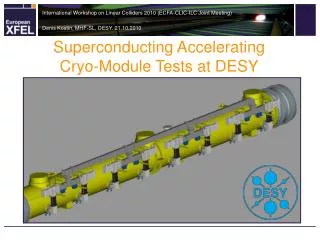
Experience from other labs • Desy (XFEL/FLASH): continuous cryostat • Maximise real estate gradient • Minimise capital cost • Safety issues (MCI, catastrophic venting) • Recent full-scale tests (after LHC sect. 3-4 incident) • Considering installation of cold valves (R&D ongoing) • FNAL (Project X) • Now addressing segmentation issues • IC-2 (CW) will be more finely segmented than IC-1 (pulsed) • JLAB (CEBAF): • Next slide
CEBAF Total of 57 independent Cryostats • Planned as full segmented • Staged construction/upgrade • Remove and replace cryomodules: ~ 1wk ! • Refurbish cryomodules: • 1 to 2 per year over next 3 years
Conclusions on sectorisation • Drivers: • Availability: • Reliability/Maintainability. Components with technical risk: • RF Coupler, single window. No in-situ repair possible • Cavity/tuner, reduced performance. No in-situ repair possible • Beam/cavity vacuum leaks. No in-situ repair possible possibility for quick replacement of cryo-module (spare) • Safety: coping with incidents: accidental loss of beam/cavity vacuum: • Cold valves not available (XFEL is considering their development) Adopt warm interlocked valves (not necessarily very fast, XFEL experience) “Segmented” layout with CDL has clear advantages in these respects • Additional advantages: • Magnets can be warm: classical “off-the shelf”, easy alignment/maintainability/upgrade • and cryo-module internal positioning requirements can ne relaxed (by 3) • Drawbacks: • Less compact layout (~10%) • More equipment (CDL, CWT, instrumentation...): • Capital cost • More complexity = less reliability? • Higher static heat loads (but dynamic loads dominate!)
Possible supporting schemes RF coupler Invar longitudinal positioner Inertia beam Fixed support Sliding support External supports (jacks)
Possible supporting schemes RF coupler Invar longitudinal positioner Inertia beam Fixed support Sliding support External supports (jacks)
Possible supporting schemes RF coupler + longitudinal positioner Inertia beam Fixed support Sliding support External supports (jacks)
Possible supporting schemes RF coupler + longitudinal positioner + vertical support Intercavity support structure External supports (jacks)
RF coupler as cavity support • Issues: • Mechanics • Cavity RF gasket • Stability w.r.t. T profile changes (gas cooling control?) • Assembly sequence/tools ...
Next steps • Refine design parameters for HP SPL (HL in particular) • Refining test objectives of the prototype • Test program: RF, cryogenics • Infrastructure needs: RF power, cryogenic test station and feedbox • Finalise choice of cryogenic scheme • Finalise operational scenarios, pressures and temperatures • Piping sizes • Continue investigation of supporting systems (RF coupler) Finalise conceptual design by mid 2010
Summary • Cryo-module prototyping is mandatory to demonstrate technology and provide a machine-representative test bed for RF and cryogenic testing • An important involvement (with H/W contributions) from external labs is now firmly engaged • The conceptual design is well progressed but still needs some months of work • RF coupler design will be reviewed in March • Detailed cryostat design should start in the 2nd half of the year • Assembly of the prototype cryo-module by end 2012