Download
1 / 18
180 likes | 322 Vues
Status of the beta=0.65 cavity for SPL linac. G. Olry, CNRS-IPN Orsay. outline. Requirements Since November 2009 (last SPL coll. meeting), studies in 2 phases Nov ‘09 – March ‘10: first design 2D ( Superfish ™) and 3D (CST Microwave Studio™) calculations on: Cell-to-cell coupling factor

E N D
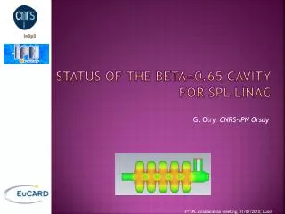
Status of the beta=0.65 cavity for SPL linac G. Olry, CNRS-IPN Orsay 4th SPL collaboration meeting, 01/07/2010, Lund
outline • Requirements Since November 2009 (last SPL coll. meeting), studies in 2 phases • Nov ‘09 – March ‘10: first design • 2D (Superfish™) and 3D (CST Microwave Studio™) calculations on: • Cell-to-cell coupling factor • Adjustments and shape sensitivity for field flatness • Positioning of the power coupler (external Q) • Mechanical design • Static load (2 bars @300K), Lorentz forces detuning • Helium tank design • April ‘10-nowadays (still on-going): new design • New parameters for vacuum load: 1.5 bars@300K • Proposal for another design:new end-groups (same as β= 1 CEA) • Conclusion & Planning
requirements GOALS Epeak/Eacc < 2.6 Bpeak/Eacc < 5.2 mT/(MV/m) + Cell-to-cell coupling factor k ≈ 1.5 % Conceptual design of the SPL II, CERN-2006-006 Starting point : 1999, EUROTRANS cavity β= 0.65 J-Luc Biarrotte, PhD Thesis, 2000, Orsay
Nov ‘09 – March ‘10: first design Réunion CM24 - 09 mars 2010
2D study (superfish) Designed with Build cavity (Paolo Pierini, INFN Milano) Poisson Superfish Interface for multi-cell cavity design. Parameterisation : The different parameters were iteratively optimised & the frequency readjusted by retuning the cell radius “R”.
2D study (superfish) • Design of the cells • Input for 3D calculations with RF coupler port 1.96 1.91 1.95 Frequency = 704.407 MHz Q0 (@ 2K ) = 3.9 1010 At βg = 0.65 r/Q = 299 Epeak/Eacc = 2.5 Bpeak/Eacc = 4.9 mT/(MV/m) -1.91 -1.91 F. Bouly (IPNO) Field Flatness : 2.55% OK
3D Calculations (MWS) 1 1 Modified for Helium vessel integration + Qext calculation 2 3 Retuned for frequency adjustment 3 2 Adjusted for field flatness
3D calculations: fields & Qext Freq = 704.3 MHz Qext = 1.09 106 Q0 (@ 2K ) = 2.8 1010 K = 1.47 % External coupling adjusted with the penetration length of the antenna F. Bouly & D. Longuevergne (IPNO) Qext≈106
3d calculations: rf parameters Evolution of the peak fields ratios as function of the reduced velocity β Atβg = 0.65 Bpk/Eacc = 5.1 mT/(MV/m) Epk/Eacc = 2.6 r/Q ≈ 300 Atβopt = 0.69 Bpk/Eacc = 4.9 mT/(MV/m) Epk/Eacc = 2.5 r/Q ≈ 325 F. Bouly (IPNO) R/Q maximum for βopt. For 0.64 < β < 0.73 → 285 < r/Q < 325
mechanical calculations • Main pb: Von Mises stresses > 50 MPa for 2 bar @ 300K with only 4 mm end-cell thickness increased to 5mm 45MPa 48MPa 28MPa 5mm 4mm 5mm free fixed P. Duchesne (IPNO) • Lorentz forces detuning with 1 stiffening ring between cells: KL< -1 Hz/(MV/m)² H-M Gassot (IPNO) 94mm beam axis
Helium vessel integration No-cooling RF coupler port No tuning system test ability ● Influence of the thermal contraction 300K4K Volume decrease : V × 0.99857 → Cavity frequency shift: +1 MHz ● Influence of the chemical etching Assumption : 100μm removed uniformly from the cavity walls → Cavity frequency shift: - 0.4 MHz
aPRIL ’10 -...: new design Réunion CM24 - 09 mars 2010
New Design: new options • Starting point: discussions with CERN & CEA get the same end-groups than those designed for the β=1 SAME INTERFACES • Main changes: • Bigger beam tubes apertures on both sides • New design of the 2 external half cells (field flatness) • New helium vessel (including the tuning system interface) • New position of the power coupler (Qext) • + • New parameters for vacuum load: 1.5 bar @300K
mechanical calculations • Von Mises stresses for 1.5 bar @ 300K < 50 MPa with 4mm (3.5mm should be ok for the inner cells) H-M Gassot (IPNO) 46 MPa Cavity walls = 4mm • Lorentz forces detuning (still 1 ring) : KL~ -1.6 Hz/(MV/m)²
Cavity integration • beta=0.65 cavity inside beta=1 helium vessel S. Rousselot (IPNO) +5 to 10mm +5 to 10mm Still on-going...
RF Design 2D and 3D studies Increased Retuned (40) (60) No changes F. Bouly (IPNO) Qext≈106 for 4mm antenna penetration
Rf parameters…still ok First Design Second Design with new end-groups
conclusions • RF Design: best compromise to fulfil requirements, especially adjusting k% & Epeak/Eacc. • Mechanical calculations: OK • 2 designs of cavity + tank Planning • July-Aug’10: Technical drawings & call for tender preparation (cavity + Niobium) • Sept-Oct’10: Call for tender • Nov’10: Choice of the manufacturer • Dec’10: Start of the fabrication • Sept’11: Cavity delivery (w/o tank) • Oct’11: Field flatness • Nov’11: Cavity + tank delivery • Dec’11: Preparation (BCP + HPR) and test (Vertical cryostat) Thank you for your attention