Turning
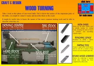
Turning is a machining process that used for machining, basically, round shapes (cylindrical, conical surfaces, and flat surfaces). These processes are usually performed by rotating the workpiece (turning) on a lathe. Turning. Objectives of machine tools (lathe). Hold the job

Turning
E N D
Presentation Transcript
Turning is a machining process that used for machining, basically, round shapes (cylindrical, conical surfaces, and flat surfaces). These processes are usually performed by rotating the workpiece (turning) on a lathe. Turning Objectives of machine tools (lathe) • Hold the job • Hold the cutter • Produce a relative movement to enable the cutting tool to generate the required surface (job).
Elements of machine tool • Structure • Slides and tool structure • Spindles and spindle bearing • Machine tool drives Types of lathes • The lathes can be classified into; • General purpose machines: center lathe, turret lathes, facing lathes, and vertical lathes. • High production machines; multiple tool lathes, semiautomatic lathes, and NC/CNC turning machines. • Single purpose and specialized lathes.
Center lathes Center lathes is used for single operation work or for miscellaneous jobbing.
Turret Lathes • It is adapted to mass production work, while the center lathe is adapted for a single operation work. • The difference between the center lathe and the turret lathe are; • The tailstock is replaced by a turret (hexagonal block), which can be may carry one or more tools. • Tools may be set up in the proper sequence for the operation. • Each station is provided with a feed stop or feed trip (help in repeatability). • Combined cut can be made. Tool on the cross slide can be used in the same time that tools in the turret are cutting. • Multiple cuts can be made from the same station at the same time. • The labors cost required is less than that required in the center lathe.
Facing Lathes • It is designed to machine shorter workpieces of great diameters (flywheel, pulleys and gears). • The workpiece is clamped on a faceplate with strap clamps. • Most of them do not have a tailstock. • The heavy weights of the large workpieces (loads) restricted the applications of facing lathe. It replaced by vertical lathes. Vertical Lathes • It is ranged from small size to large size for heavy workpieces (up to 25 m in diameter). • The clamping plates, in it, are horizontal and rotate around the vertical axis. • It is used in the heavy engineering industry for machining the parts of hydraulic turbines, generators, etc.
Cutting and feed movements • Generating machining • These jobs are produced with three cutting motions; • Rotary motion of workpiece about fixed axis (cutting motion, speed) with one of the following; • Linear motion of tool parallel to the axis of rotation (feed motion) and depth of cut in the third direction (depth of cut). Cases are such as a, d, k, f, h, and l. • Linear motion of tool at right angle to the axis of rotation (feed motion) and depth of cut in the third direction (depth of cut). Cases are such as e and j. • Linear motion of tool at intermediate angle to the axis of rotation (feed motion) and depth of cut in the third direction (depth of cut). Cases are such as b and c.
Forming machining Rotary motion of workpiece about fixed axis (cutting motion, speed) with feed motion toward the workpiece without depth of cut. Cases are such as g, I, and k. • To achieve a high degree of accuracy and surface finish; • Prevent the work from deflection • Constant feed rate to produce a uniform and good surface finish. • The depth of cut must be controlled to a high degree of accuracy.
Work-holding methods: In the cylindrical work, all diameters should be concentric and all faced surfaces should be square to the cylinder axis. The best way is to perform as many operations as possible at one setting. • The self –centering chuck (three jaws chuck); p98, fig 4-3. The jaws and slots are numbered and assembled in sequence or they will not centralize correctly. This method is not preferred for accurate setting or concentricity. The three-jaw, self-centring chuck: (a) construction; (b) external and internal jaws
The independent four jaws; p100, fig 4-4. It provides the facility of setting work off-center to produce eccentric workpiece. The concentric diameter(s) are produced first then adjust the chuck for eccentricity by a dial gauge. The dial gauge readings must vary by twice the amount of eccentricity required. the chuck is adjusted until the DTI maintains a constant reading whilst the chuck is revolved; The four-jaw chuck
The collet chuck, p100, fig 4-5. It provides for a certain diameter, high repeatability, too small griping length (it is possible to cut close to the collet), it is made of medium carbon steel and is hardened and spring tempered so that when unlocked it will spring open and release the work. To enable it to close on the work three or four slots are made. (c) push out type collet (a and b) draw in type collet
Holding work between centers. P104, fig 4-6. It used for solid work. It should have a center hole in each end. There are two centers, live center attaché to the headstock and dead center attach to the tail stock. Virtually exact repeatability of position. To drive the work catch plate with a driving pin is fitted in the spindle nose and a work carrier (driving dog) is attach to the work. The parallelism should be checked. For hollow shafts a mandrel can be used, fig4-7
The faceplate; fig4-8 • External work supports; Traveling support (steady) fig4-9 Fixed support (steady) fig4-10, used when the tailstock can not be used (the work is hollow at the end near the tailstock or that end is to be bored to size). The pads or rests are act as bearing and are usually made of brass.
Taper turning • Setting the tail stock off-center (adjusting the axis of rotation) • Offset distance Where; L is the full length of the workpiece D is the largest diameter of the workpiece d is the smallest diameter of the workpiece l is the length of the tapered surfaces.
Using the compound top slide (for any angle but the length of travel is limited and hand feed must be used), give limited accuracy. • Calculate the inclination angle? • Using form tool. • What is the tool inclination angle?
Taper turning attachment, the lead screw of the cross slide is released, so the control of depth of cut is taken from the sliding block around the guide bar, which is inclined with the required angle.
The effect of incorrect tool setting on taper turning; with low tool setting; • The taper angle will be incorrect • The taper will not be straight With 2 mm low, the error in the radius is 0.02 mm (p112&113)
Driver Pitch of work = Driven Pitch of lead screw Screw cutting in the lathe The form of the thread is coped from the tool shape. The tool should be ground to the correct shape (angle and nose radius and zero top rake angle). Use the screw cutting plate gauge to check the correct shape of the tool and to set it to the correct position with respect to the workpiece. Generating the thread helix; p116 Select of gear trains in the Screw cutting Use gears with no. of teeth between 20 and 120 and step 5 teeth.
Cutting Parameters 1- Depth of cut d =(Do –Df)/2. D.o.c is usually taken as 3-5 mm for rough turning and 0.8 to 1.6 mm for finish turning. 2- Cutting speed mm/min where V= 3.14 DN 3- feed per rev (f mm/rev) where feed rate fr= Nf Feed is usually taken as 0.3-1.5 mm for rough turning and 0.1 to 0.8 mm for finish turning. Time to cut =L/fr Volumetric rate of metal removal = vfd Each metal has an optimum speed v
It is required to turn a 90 mm. diameter and 250 mm. length bar to the shown dimension with speed = 90m/min, feed rate = 0.38 mm/rev. and depth of cut = 5mm. The approach and over travel = 3 mm. • Choose the suitable method to hold this workpiece. • Find the machining time required to machine this workpiece. All dimensions in mm. • Notes; • What does happen when; • D.O.c =3 • Work length is 320mm holding length is 50 mm.
Determine the number of teeth for screw cutting train to cut thread of pitch 0.7 mm given that the lathe leadscrew pitch is 4 mm and the available gears have 20 to 120 teeth with step of 5 teeth. Thread cut