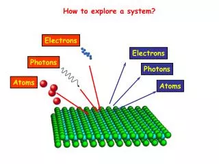
How to explore a system?
How to explore a system?. Electrons. Electrons. Photons. Photons. Atoms. Atoms. How to explore a system?. Electrons. Electrons. Photons. With different kinetic energies. Electron Energy Analyzers. Detect the charged particles for a given energy range with good

How to explore a system?
E N D
Presentation Transcript
How to explore a system? Electrons Electrons Photons Photons Atoms Atoms
How to explore a system? Electrons Electrons Photons With different kinetic energies
Electron Energy Analyzers Detect the charged particles for a given energy range with good energy (and space) resolution Retarding Field Analyzer (RFA) Cylindrical Mirror Analyzer (CMA) Hemispherical Analyzer (HA)
N(E) E0 + ΔE E0 Electron Energy (eV) Electron Energy Analyzers Energy distribution curve: response of the system Separate the electrons with a defined energy band
V0 Retarding Field Analyzer (RFA)
V0 Retarding Field Analyzer (RFA) N(E) V0 = Retarding potential E0 = eV0 = Pass energy Current to screen N(E) E0 + ΔE E0 To obtain N(E) one has to differentiate Electron Energy (eV)
Retarding Field Analyzer (RFA) Modulation
First harmonic N(E) Second harmonic dN(E)/dE RFA: poor sensitivity and energy resolution No angular resolution
Electrostatic deflection analyzers Cylindrical Mirror Analyzer (CMA) Hemispherical Analyzer (HA) Dispersing field Deflection is function of electron energy Concept Energy band pass - v1 Electrons have angular spread around the entrance direction v2 v1 + Electrons with same v will be deflected by different amounts Degradation of energy resolution
Cylindrical Mirror Analyzer (CMA) e- cross the inner cylinder through a slit experience the field –V of the outer cylinder go to second slit and and arrive in F V=deflecting voltage between cylinders consider an e- arriving at an angle 0 with e- energy work of the e.m. field on e- e- energy inside cylinder
Cylindrical Mirror Analyzer (CMA) The trajectory for which the e- is focussed is a solution of the equation of motion (cyl. coord.) The maximum deflection depends on the entrance angle, and shows that K0 depends also on Electrons with same E will be deflected by different amounts depending on the entrance angle focussing condition
Cylindrical Mirror Analyzer (CMA) The numerical solution shows that for a single K0 there are two values of entrance angle This means that in general there are two focussing distances For K0 = 1.31 the two focal distances merge into one A single focussing length L correspond to different acceptance angles (see curve (c)) L = 6.130 r1 High sensitivity with one pass energy
Cylindrical Mirror Analyzer (CMA) L The emission angle determines three main factors (a) source-image distance on the common cylinders axis (L) (b) the deflecting voltage for particles with energy E (c) the required ratio between the cylinders radii For 0= 42°18.5' the first spherical aberration term = 0
Cylindrical Mirror Analyzer (CMA) For small and small E, the shift in the axis crossing point is (Taylor series) r1 = inner cylinder One looks for L 0 Neglecting the product Base resolution
Cylindrical Mirror Analyzer (CMA) Transmission = fraction of space in front of the sample intercepted by the analyser analyser transmission For a fixed slit, T does not depend on energy
Cylindrical Mirror Analyzer (CMA) The image of the source can be reduced by inserting a slit before the focus that reduces the coefficients of 3 by a factor of 4 Finite source + ring slit of width W and radius r1 For a given slit, T does not depend on energy while EB E So the energy resolution is not constant with E peak area (T x EB) N(E) but (T x EB) E E0 + ΔEB E0 Peak area N(E)xE The spectrum contains the intensity-energy response function of the analyser Electron Energy (eV)
Concentric Hemispherical Analyzer (CHA) Two spherical electrodes 1/r electrostatic potential Electrons are injected with energy eV0 at slit S in the point corresponding to radius R0 The condition to allow e- to describe the central orbit is (point source) Focussing condition in F For R1=115 R2=185 mm K = 1.013
Concentric Hemispherical Analyzer (CHA) e- forming angle with tangential direction e- with energy E with respect to E0 Shift in the radial position Considering two slits of width W1 and W2 Base resolution R0=150 mm W1 = W2 = 3 mm R0=150 mm W1 = W2 = 1 mm The resolution is mainly determined by the central hemispherical radius
Concentric Hemispherical Analyzer (CHA) Transmission If the sample is at the position of the slit W1, we assume W1 = 0 and neglect so the angular acceptance in the plane depends on the slit W2 We also have to consider the angular acceptance in the plane perpendicular to the screen () Transmission of the analyser In analogy to the CMA Worse than CMA (lower transmission and resolution)???
Concentric Hemispherical Analyzer (CHA) Problem: sample cannot be at position of slit 1 solutions Use lenses to focus beam at slit 1 Reduce the analyzer angle to 150° • r = source radius • = cone semiangle of source E = e- energy at the source rp = source image at entrance slit W1 • = cone seminagle of image Ep = e- energy at the image Helmoltz-Lagrange equation Lens magnification Retarding ratio = cone semiangle of source defined by the lens
Concentric Hemispherical Analyzer (CHA) What is defining the transmission of the analyser? Consider the cone with semiangle • The lens defines the transmission • The lens defines the transmission in and the spectrometer in • The spectrometer defines the transmission The CHA is designed to accept of about 4-5° (similar to = 5)
Electrostatic lenses Optical ray refraction Electron refraction e speed Refraction index electrostatic potential Snell’s law: n1 sin1 = n2 sin2 The potential changes abruptly at the interface: only the perpendicular component of the momentum changes
Electrostatic lenses For real lenses there are no abrupt changes in the potential, as shown in the figure e path Equipotential lines But one can assume the asymptotic behavior of the electron trajectories to make use of the lens equations Transverse magnification Angular magnification Helmoltz-Lagrange equation Conservation of brightness
Electrostatic lenses Lenses has the effect to change the kinetic energy of the beam Focussing Defocussing Focussing Electron lenses formed using metallic apertures.
Electrostatic deflection analyzers CMA Energy resolution E0 = pass energy ΔEB = Emin-Emax transmitted s = slit width , angular apertures CHA
Electrostatic deflection analyzers Geometry of the acceptance slit is very different CHA 5° CMA 6° 42.3° Small signal Compatible with simple electrostatic aperture and tube lenses Long focal distance Radius 100 - 150 mm Res. Power about 1000-5000 Working distance about 25-50 mm Large signal Non compatible with simple electrostatic aperture and tube lenses Short focal distance Cyl diam 100 - 150 mm Res. Power about 200 Working distance about 5 mm
Electrostatic deflection analyzers Detection mode Single Multi Scan over voltages acquiring the position and therefore the energy of the electrons with different trajectories Scan over voltages acquiring counts at each energy E(V) E1 E2 E3
Electrostatic deflection analyzers Detection mode Multi Channeltron Channelplates + ccd camera Scan over voltages acquiring the position and therefore the energy of the e- with different trajectories
Electrostatic deflection analyzers Mode of operation No pre-retarding potential Pre-retarding potential Vary the pre-retarding potential and not E0 Vary E0 with Vscan EB is constant EB is increasing with energy
Hemispherical Analyzer of Electron Kinetic Energy
Lay-out of an Electron Spectroscopy Experiment Based onto a Double-Pass Cylindrical Mirror Analyzer
Hemispherical Analyzer of Electron Kinetic Energy with Entrance Optics Designed for Lateral Resolution
Electron Source and Energy Monochromator and Electron Kinetic Energy Analyzer HREELS Apparatus
Electron Multiplier Detection efficiency 80 % Gain 108
Microchannel plates Thin Si-Pb oxide glass wafers Channel density 105 cm-1 Channel walls act as electron multipliers Detection efficiency 80 % Gain 105 - 108