Download
1 / 63
710 likes | 1.07k Vues
Tolerance Analysis of Compliant Metal Plate Assemblies Considering Welding Distortion. Hyun Chung, Ph.D. Postdoctoral Research Associate Dept. of Naval Architecture and Marine Engineering University of Michigan August 28 2006. Overview. Motivation and Perspective Research Objective

E N D
Tolerance Analysis of Compliant Metal Plate Assemblies Considering Welding Distortion Hyun Chung, Ph.D. Postdoctoral Research Associate Dept. of Naval Architecture and Marine Engineering University of Michigan August 28 2006
Overview • Motivation and Perspective • Research Objective • Background • Current Research • Inherent strain method • Mechanistic variation simulation • Three-bar model • Modified method of influence coefficients • Design Implication • Conclusion and Future Work Recommendations
Motivation and Perspective (1) • Ship block construction processes • Thick metal plates ( 10mm~30mm ) • Compliant behavior due to large sizes • Required accuracy is about 1/100,000 • Joined primarily by heat-flux welding that causes significant distortions • Intermediate products that fail to meet the tolerance requirements are not scrapped, but reworked • Dimensional quality of intermediate products not only affects final product quality but also productivity of shipyard
Motivation and Perspective (2) • Excessive variation due to warpage, shrinkage, etc may lead to tolerance stack-up that results in increased assembly stresses • Traditional tolerance analysis usually relies upon a rigid body assumption, which cannot explain compliant characteristics of metal plate assembly • Various research work on tolerance analysis and tolerance synthesis for automotive body and machining production [S.C.Liu and S.J.Hu 1997] • Assembly sequence can positively affect the welding distortions during assembly process without any mitigation processes [ J.K.Roh and J.G.Shin 1999]
Motivation and Perspective (3) • Statistically predict dimensional quality of ship block assemblies • Non-nominal plate geometry • Compliant metal plates • Welding distortion • Fast and efficient calculation
Motivation and Perspective (4) • Ship block construction processes (cont.) • Research has provided a means to determine statistical variation in ship block assembly including distortion of welded structure in minutes instead of hours with equivalent accuracy compared to current methods. • Usually requires many runs and table below shows research benefit per run
Motivation and Perspective (5) • Different assembly sequences make different dimensional qualities • Welding distortions are heavily affected by structural and thermal boundary conditions • Different sequences make different boundary conditions
Research Objectives (1) • Combination of tolerance analysis and finite element analysis to develop compliant assembly model of ship block construction • Fast and efficient calculation • The effect of heat-flux welding deformation and residual stresses considered in variation simulation for compliant assemblies • Identification of factors that control the deformation of non-nominal plate assemblies after being welded
Research Objectives (2) • Validation of compliant assembly model through ship block assembly example
Background (2) • Variation simulation • Traditional variation analyses • Mechanistic variation analysis • Method of Influential Coefficients • Welding distortion prediction • Simplified load • Inherent strain method • 3D thermo-elasto-plastic FEA • Statistical representation of plate part variations • B-Spline Beam/Plate element
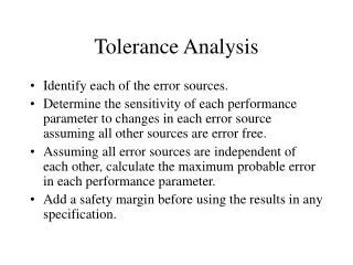
Background (3) • Traditional variation analysis • Worst case [Greenwood and Chase 1988] • Assumes that all parts are built to its extreme values • Too restrictive • Statistical analysis [Chase and Parkinson 1991] • Variations of parts are specified as statistical distribution • Root Sum Square (RSS) • Monte-Carlo simulation [Craig 1988, Doepker and Nies 1989, Early and Thomson 1989] • Straightforward • Computationally expensive
Background (4) • Traditional variation analysis (cont.) • Individual parts are considered as rigid bodies • Aggregate behaviors are determined by geometric and/or kinematic relations • Assembly sequence does not affect the dimensional variations of final product • Mechanistic variation simulation [S.C.Liu and S.J.Hu 1995] • Compliant sheet metal assemblies • Sequence of assembly can affect the tolerance of final product [ Liu, Hu and Woo 1995]
Background (5) • Method of Influence Coefficients as the more efficient method of calculating variations due to compliant assemblies [Liu and Hu 1995] • Statistically combining the sensitivity matrix with root sum square method to determine mean and standard deviation, without Monte-Carlo simulation • Use of sensitivity matrix to interpret geometrical imperfection to equivalent external forces • Applied only to simple geometries • Valid only in elastic deformation range • Welding distortions not considered
Background (6) • Welding deformation prediction • Simplified load method • Simple rule-of-thumb based on previous production data • Only applicable to existing cases • Cannot predict transient shape change • Numerical simulation method (Inherent strain/load method) • Assumption of inherent strain distribution • Cannot predict transient shape change • 3-Dimensional thermo-elasto-plastic FEA • Computationally expensive • Can predict transient shape, temperature, stress/strain distribution change
Background (7) • Statistical representation of plate part variations • Random Bézier Curve [Merkley K., 1998] • Good for plate gap modeling • Not applicable to plate shape • Finite Element Mesh • Straightforward • Cannot accurately represent slope and curvature • B-Spline Beam/Plate Element • B-Spline shape functions • Not applicable to statistical shapes
Inherent Strain Method (1) • Originally developed to predict residual stress within structure [Ueda, 1975] • Equivalent to ‘Eigenstrain’ [Mura, 1982] • Hybrid method (partially analytic, partially experimental) • Inelastic and non-compatible strain that accounts for plastic deformation of the body • Defined as
Inherent Strain Method (2) • What are the stress/strain states when the temperature is increased by 1 degree given that the individual bars have different thermal expansion coefficients? • Sequence • Stress free initial state • Stress free state after unit temperature increase • Final state • Total strain = elastic strain + inherent strain • Residual stress
Inherent Strain Method (3) • Three-bar model for welding distortion prediction • Welding distortion is caused by highly non-uniform temperature distribution in the welded region • Only middle bar undergoes temperature change • Elastic-perfect plastic material assumed • Stress history in the middle bar • OA: elastic compression • AB: plastic compression • BC: elastic tension • CD: plastic tension
Inherent Strain Method (7) • Based on three-bar model, welding distortion is only dependant on • Material • Maximum temperature • Degree of restraints, • DOR is determined by • Plate thickness • Welding type • Butt or fillet welding • Welding conditions
Inherent Strain Method (8) • Equivalent loading based on Inherent Strain [Lee, 2002] • Equivalent loads are forces and moments relevant to the deformation modes of welded plates, which are the integration of inherent strain distribution
Inherent Strain Method (9) • Compared to 3D FEA result • ~1/500 computation time • Relatively high accuracy • Longer weld line results in higher accuracy
Mechanistic Variation Simulation (1) • Method of Influence Coefficients [Liu and Hu, 1995] • Elastic deformation only • No welding distortion (spot welding) • Linear mapping between part variation and assembly deviation • The sensitivity matrix is obtained by unit force response
Mechanistic Variation Simulation (2) • Method of Influence Coefficients [Liu and Hu, 1995] • Small variations are assumed • Unit force is applied at j-th source of variation • Deformation under unit force is calculated by FEM • Obtain the influence of j-th variation to N-th node • Spring-back is calculated by FEM
Current Research How part variation affects welding distortion? How welding distortion affects variation simulation?
Three Bar Models (1) • Clamped-clamped 3-bar model with initial part variation • The structure is clamped to its nominal length and undergoes temperature changes, and then clamping is released • Displacement is confined • Model for the region adjacent to clamping devices • Spring-clamped 3-bar model with initial variation • External force is applied to the structure and the structure undergoes temperature changes, and then the external force is removed • Clamping force is constant • Model for the region far from clamping devices
Three Bar Models (2) • Procedure • Step1: initial variation • Step2: clamping to nominal position • Elastic deformation • Step3: welding • Elastic state during heating • Plastic state during heating • Elastic state during cooling • Plastic state during cooling • Step4: releasing clampings • Elastic deformation
Modified Variation Simulation (1) • Modified method of influence coefficients • Initial part variation affects welding distortion as it slightly changes degree of restraints • Due to the Linearity between the residual strain and initial variation, the welding distortion term of non-nominal parts can be replace as the welding distortion term of nominal parts • The differences could be absorbed in the sensitivity matrix based on the value found on the inherent strain chart
Plate variation representation (1) • Cubic B-Spline finite element • New basis function that require two more control points is adopted • Equally spaced splines
Plate variation representation (2) • Cubic B-Spline plate element • Displacement where
Plate variation representation (3) • Cubic B-Spline plate element • Strain-displacement relationship • Strain-stress relationship
Plate variation representation (4) • Cubic B-Spline plate element • Stiffness matrix with respect to Spline parameters • Displacement relationship
Plate variation representation (5) • Cubic B-Spline plate element • Stiffness matrix with respect to global coordinate system where is square matrix
Plate variation representation (6) • Cubic B-Spline plate element example • Plate deflection under concentrated load (C-C-C-C) and (S-S-S-S)