Fast mode decision for Inter Mode Selection in H.264/AVC Video Coding
710 likes | 1.03k Vues
Fast mode decision for Inter Mode Selection in H.264/AVC Video Coding. By Amruta Kulkarni Under Guidance of DR. K.R. RAO. Contents. Need for video compression Motivation Video coding standards, video formats and quality Overview of H.264

Fast mode decision for Inter Mode Selection in H.264/AVC Video Coding
E N D
Presentation Transcript
Fast mode decision for Inter Mode Selection in H.264/AVC Video Coding By Amruta Kulkarni Under Guidance of DR. K.R. RAO
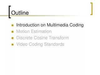
Contents • Need for video compression • Motivation • Video coding standards, video formats and quality • Overview of H.264 • Complexity reduction algorithm for inter mode selection • Experimental results • Conclusions • References
Needfor Video Compression • It reduces both storage and bandwidth demands. • Insufficient resources to handle uncompressed videos. • Better proposition is to send high-resolution compressed video than a low-resolution, uncompressed stream over a high bit-rate transmission channel.
Motivation [2] Removing redundancy in a video clip Only a small percentage of any particular frame is new information Highly complex process • Reduce the overall complexity suitable for handheld devices
Timeline of Video Development [10] Inter-operability between encoders and decoders from different manufacturers Build a video platform which helps to interact with video codecs, audio codecs, transport protocols, security and rights management in well defined and consistent ways
OVERVIEW OF H.264 / AVC STANDARD • Built on the concepts of earlier standards such as MPEG-2 and MPEG-4 Visual • Achieves substantially higher video compression and has network friendly video representation • 50% reduction in bit-rate over MPEG-2 • Error resilience tools • Supports various interactive (video telephony) and non-interactive applications (broadcast, streaming, storage, video on demand)
H.264/MPEG-4 Part 10 or AVC [2, 5] • Is an advanced video compression standard, developed by ITU-T Video Coding Experts Group(VCEG) together with ISO/IEC Moving Picture Experts Group(MPEG). • It is a widely used video codec in mobile applications, internet ( YouTube, flash players), set top box, DTV etc. • A H.264 encoder converts the video into a compressed format(.264) and a decoder converts compressed video back into the original format.
How does H.264 codec work ? • An H.264 video encoder carries out prediction, transform and encoding processes to produce a compressed H.264 bit stream. The block diagram of the H.264 video encoder is shown in Fig 1. • A decoder carries out a complementary process by decoding, inverse transform and reconstruction to output a decoded video sequence. The block diagram of the H.264 video decoder is shown in Fig 2.
H.264 encoder block diagram Fig. 1 H.264 Encoder block diagram[7]
Bitstream Input + Video Output Inverse Quantization & Inverse Transform Deblocking Filter Entropy Decoding + Intra/Inter Mode Selection Picture Buffering Intra Prediction Motion Compensation H.264 decoder block diagram Fig.2 H.264 decoder block diagram [2]
Slice Types [3] I (intra) slice – contains reference only to itself. P (predictive) slice – uses one or more recently decoded slices as a reference (or prediction) for picture construction. B (bi-predictive) slice – works similar to P slices except that former and future I or P slices may be used as reference pictures SI and SP or “switching” slices may be used for transitions between two different H.264 video streams.
Profiles in H.264 • The H.264 standard defines sets of capabilities, which are also referred to as “Profiles”, targeting specific classes of applications. Fig. 3. Different features are supported in different profiles depending on applications. Table 1. lists some profiles and there applications. Table 1. List of H.264 Profiles and applications[2]
Profiles in H.264[9] Fig. 3 Profiles in H. 264[9]
Intra Prediction • I – pictures usually have a large amount of information present in the frame. • The spatial correlation between adjacent macro-blocks in a given frame is exploited. • H.264 offers nine modes for intra prediction of 4x4 luminance blocks. • H.264 offers four modes of intra prediction for 16x16 luminance block. • H.264 supports four modes similar to 16x16 luminance block for prediction of 8x8 chrominance blocks.
Intra prediction Fig.4 16x16 intra prediction modes [11] Fig. 5 4x4 Intra prediction modes [11]
Inter Prediction [5] • Takes advantage of the temporal redundancies that exist among successive frames. • Temporal prediction in P frames involves predicting from one or more past frames known as reference frames.
Motion Estimation/Compensation • It includes motion estimation (ME) and motion compensation (MC). • ME/MC performs prediction. A predicted version of a rectangular block of pixels is generated by choosing another similarly sized rectangular block of pixels from previously decoded reference picture. • Reference block is translated to the position of current rectangular block (motion vector). • Different sizes of block for luma: 4x4, 4x8, 8x4, 8x8, 16x8, 8x16, 16x16 pixels.
Inter prediction Fig. 6 Partitioning of a MB for motion compensation [5]
Integer Transform and Quantization • Transform: • Prediction error block is expressed in the form of transform co-efficients. • H.264 employs a purely integer spatial transform, which is a rough approximation of the DCT. • Quantization: • Significant portion of data compression takes place. • Fifty-two different quantization step sizes can be chosen. • Step sizes are increased at a compounding rate of approximately 12.5%.
De-blocking Filter and Entropy Coding • De-blocking filter: • Removes the blocking artifacts due to the block based encoding pattern • In-loop de-blocking filter • Entropy coding: • Assigning shorter code-words to symbols with higher probabilities of occurrence, and longer code-words to symbols with less frequent occurrences. • CAVLC and CABAC
FAT (Fast Adaptive Termination) for Mode Selection [9] • The proposed fast adaptive mode selection algorithm includes the following: • Fast mode prediction • Adaptive rate distortion threshold • Homogeneity detection • Early Skip mode detection
Fast mode prediction • In H264/ AVC video coding is performed on each frame by dividing the frame into small macro blocks from up-left to right-bottom direction. • The spatial macro blocks in the same frame generally have the similar characteristics such as motion, detailed region. • For example, if most of the neighboring macro blocks have skip mode, that means the current macro block has more chance of having the same mode. • Temporal similarity also exists between the collocated macro blocks in the previous encoded frame.
Fast mode prediction • Fig. 7 shows the spatial macro blocks, the current macro block X has similar characteristics with its neighboring macro blocks from A through H. • In Fig. 8 shows the temporal similarity between current and collocated macro block PX in the previous frame and its neighbors. Fig. 8 Temporal Neighboring blocks [8] Fig. 7 Spatial Neighboring blocks [8]
Fast mode prediction • A mode histogram from spatial and temporal neighboring macro blocks is obtained, we select the best mode as the index corresponding to the maximum value in the mode histogram. • The average rate-distortion cost of each neighboring macro block corresponding to the best mode is then selected as the prediction cost for the current macro block.
Rate Distortion Optimization • Rate–distortion optimization (RDO) is a method of improving video quality in video compression. The name refers to the optimization of the amount of distortion (loss of video quality) against the amount of data required to encode the video, the rate. • Macro block parameters : QP(quantization parameter) and Lagrange multiplier (λ) • Calculate : λMode= 0.85*2(QP-12)/3 • Then calculate cost, which determines the best mode, • RDcost = D + λMODE * R, • D – Distortion • R - bit rate with given QP • λ – Lagrange multiplier • Distortion (D) is obtained by SAD (Sum of Absolute Differences) between the original macro block and its reconstructed block. • Bit rate(R) includes the bits for the mode information and transform coefficients for macro block . • Quantization parameter (QP) can vary from (0-51) • Lagrange multiplier (λ) a value representing the relationship between bit cost & quality.
Adaptive Rate Distortion Threshold • RDthres for early termination is dependent on RD pred which is computed according to spatial and temporal correlations. • RDthres also depends on the value of β modulator. • Thus, rate distortion threshold is given by, Rdthres = (1+ β) x RD pred • β modulator provides a trade-off between computational efficiency and accuracy.
Threshold selection • Adaptive Threshold I: RD thres = RD pred x (1-8xβ) • Adaptive Threshold II: RD thres = RD pred x (1+10xβ) • The threshold is adaptive as it depends on the predicted rate distortion cost derived from spatial and temporal correlations. • Where, β is the modulation Coefficient, and it depends on two factors namely quantization step (Qstep) and block size (N and M).
Homogeneity Detection • Smaller block sizes like P4x8, P8x4 and P4x4 often correspond to detailed regions and thus requires much more computation when compared to larger block sizes. • So, before checking smaller block sizes it is necessary to check if a P8x8 block is homogeneous or not. • The method adopted to detect homogeneity is based on edge detection. • An edge map is created for each frame using the Sobel operator [27].
Homogeneity Detection • For each pixel pm, n, an edge vector is obtained Dm,n( dxm,n, dym,n) • dxm, n = pm-1, n+1 + 2 * pm, n+1 + pm+1, n+1 - pm-1, n-1 – 2 * pm, n- 1 - pm+1, n-1 (1) • dym,n = pm+1, n-1 + 2 * pm+1, n + pm+1, n+1 - pm-1, n-1 – 2 * pm-1, n - pm-1, n+1 (2) • Heredxm, n and dym, n represent the differences in the vertical and horizontal directions respectively. • The amplitude Amp (D (m, n)) of the edge vector is given by, • Amp (D (m, n)) = │dxm, n │+ │dym, n │ (3) • A homogeneous region is detected by comparing the summation of the amplitudes of edge vectors over one region with predefined threshold values [30]. In the proposed algorithm, such thresholds are made adaptive depending on the amplitude of left, up blocks and mode information.
Homogeneity Detection • The adaptive threshold is determined as per the following four cases: • Case 1: If the left block and the up block are both P8x8 • Case 2: If the left block is P8x8 and up block is not P8x8 • Threshold =
Homogeneity Detection • Case 3: If the left block is not P8x8 and up block is P8x8 • Threshold = • Case 4: If the left block is not P8x8 and up block is not P8x8
FAT Algorithm [8] Fig. 9 FAT algorithm [8]
FAT Algorithm • Step 1 : If current macro block belongs to I slice, check for intra prediction using I4x4 or I16x16,go to step 10 else go to step 2. • Step 2 : If a current macro block belongs to the first macro block in P slice check for inter and intra prediction modes, go to step 10 else go to step 2. • Step 3: Compute mode histogram from neighboring spatial and temporal macro blocks, go to step 4. • Step 4 : Select prediction mode as the index corresponding to maximum in the mode histogram and obtain values of Adaptive Threshold I and Adaptive Threshold II, go to step 5. • Step 5 : Always check over P16x16 mode and check the conditions in the skip mode, if the conditions of skip mode are satisfied go to step 10, otherwise go to step 6.
FAT Algorithm • Step 6 : If all left, up , up-left and up-right have skip modes, then check the skip mode against Adaptive Threshold I if the rate distortion is less than Adaptive Threshold I , the current macro block is labeled as skip mode and go to step 10, otherwise, go to step 7. • Step 7 : First round check over the predicted mode; if the predicted mode is P8x8, go to step 8; otherwise, check the rate distortion cost of the predicted mode against Adaptive Threshold I. If the RD cost is less than Adaptive Threshold I, go to step 10; otherwise go to step 9. • Step 8 : If a current P8x8 is homogeneous, no further partition is required. Otherwise, further partitioning into smaller blocks 8x4,4x8, 4x4 is performed. If the RD of P8x8 is less than Adaptive Threshold I , go to step 10; otherwise go to step 9.
FAT Algorithm • Step 9 : Second round check over the remaining modes against Adaptive Threshold II : If the rate distortion is less than Adaptive Threshold II; go to step 10; otherwise continue check all the remaining modes, go to step 10. • Step 10 : Save the best mode and rate distortion cost.
CIF and QCIF sequences • CIF (Common Intermediate Format) is a format used to standardize the horizontal and vertical resolutions in pixels of Y, Cb, Cr sequences in video signals, commonly used in video teleconferencing systems. • QCIF means "Quarter CIF". To have one fourth of the area as "quarter" implies the height and width of the frame are halved. • The differences in Y, Cb, Cr of CIF and QCIF are as shown below in fig.6. [16] Fig.10 CIF and QCIF resolutions(Y, Cb, Cr ).
Results • The following QCIF and CIF sequences were used to test the complexity reduction algorithm. [10] • Akiyo • Foreman • Car phone • Hall monitor • Silent • News • Container • Coastguard
Test Sequences Akiyo News Foreman Container Coastguard Car phone
Test Sequences Hall monitor Silent
Experimental Results • Baseline profile • IPPP type. • Various QP of 22,27, 32 and 37. • QCIF -30 frames CIF - 30 frames • The results were compared with exhaustive search of JM in terms of the change of PSNR, bit-rate, SSIM, compression ratio, and encoding time. • Intel Pentium Dual Core processor of 2.10GHz and 4GB memory.
Experimental Results • Computational efficiency is measured by the amount of time reduction, which is computed as follows: • Delta Bit rate is measured by the amount of reduction which is computed by, • Delta PSNR (Peak Signal to Noise Ratio) is measured by the amount of reduction which is computed by,
Quality • Specify, evaluate and compare • Visual quality is inherently subjective. • Two types of quality measures : • Objective quality measure- PSNR, MSE • Structural quality measure- SSIM [29] • PSNR - most widely used objective quality measurement PSNRdB = 10 log10 ((2n − 1)2 / MSE) where, n = number of bits per pixel, MSE = mean square error • SSIM – SSIM emphasizes that the human visual system is highly adapted to extract structural information from visual scenes. Therefore, structural similarity measurement should provide a good approximation to perceptual image quality.